Hi,
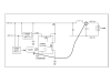
If I was trying to use provide a soft-start to a High Voltage bus, i was thinking of PWMing the bus FET and using an inductor to limit the inrush current while the Load's input Caps are charging. I couldnt find any mosfet or igbt gate driver chips that would stay on 100% duty cycle after the soft start, so was thinking of doing something like this pics. Does this seem like it'd work? Anyone know of a half-bridge IC that would work, and would also have the ability to switch on the high side permanently once i'm done with the soft-start? Or would i need to just turn off the chip completely, and provide control for another high side switch to keep the +315V at the bus FET gate?
And im having no luck finding the 600 to low voltage DC converters.
Thanks alot!