Continue to Site

Welcome to our site!

Electro Tech is an online community (with over 170,000 members) who enjoy talking about and building electronic circuits, projects and gadgets. To participate you need to register. Registration is free. Click here to register now.

  • Welcome to our site! Electro Tech is an online community (with over 170,000 members) who enjoy talking about and building electronic circuits, projects and gadgets. To participate you need to register. Registration is free. Click here to register now.

High side current sense in 6W Buckboost LED driver

Status
Not open for further replies.

Flyback

Well-Known Member
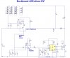
In the attached 6W Buckboost LED driver schematic, the high-side current sense is referred down to ground via the common base connected PNP (FMMT560Q).

We are worried about situations in which the collector and emitter currents of the PNP would start to differ significantly. (eg, at low [eg sub 1mA] collector currents, or at high temperature, where collector-base leakage current may make collector and emitter currents differ.)

Can you confirm, in this schematic, that collector and emitter currents are always likely to remain close in magnitude?

I mean, the PNP in the schematic presented cannot saturate because its Base-Collector junction cannot get forward biased in this schematic and setup.

It seems weird though that such a simple method of referring a sense signal down from the high side is not more widely used? I mean, its just basically a cheap PNP transistor as shown in the schematic attached. It makes you search for some hidden gremlin in this PNP method.

Schematic and LTspice simulation attached
 

Attachments

  • 6W Buckboost LED driver.asc
    10.3 KB · Views: 93
  • 6W Buckboost LED driver.jpg
    6W Buckboost LED driver.jpg
    136.2 KB · Views: 168
It seems weird though that such a simple method of referring a sense signal down from the high side is not more widely used?
Simple? This is simple. I have used it in production.
Also I added a soft start because your circuit has power on over shoot.
upload_2018-4-24_6-12-55.png

Using your circuit, I can set the LEDs on ground for no cost if that helps.
 

Attachments

  • Buckboost LED driver 6W-ron1.asc
    12.5 KB · Views: 90
the only reason why the collector-emitter current would change is if there is a change in gain of the pnp transistor. Why not use a darlington pair then you can be sure the gain will be high? Failing that, the LTC6102 works up to 100V and senses on the high side, so you dont have to generate the boosted 5V supply to power U1. That would be a more sensible way of doing this.
 
Here is the circuit, using the LT6101. The circuit 'hangs down' from the high side rail. There is a Zener diode that clamps the voltage across the LT6101 to 33V and a resistor, R4, that provides bias for the Zener. The LT6101 outputs a current. This current feeds into the emitter of Q2. If the gain of Q2 is low, then Q2 will have a large base current. Since the collector current = Emitter current - base current, then a large base current will present a large error. However, with a Darlington configuration, this base current feeds into the emitter of the second transistor Q1. This emitter current (of Q1) is much smaller than the emitter current of Q2.

Q1's collector current = Emitter current - base current. However, the base current of Q2 is now the emitter current of Q1, and most of this feeds into the output resistor R3. Therefore the 'error current' of Q2 (its base current) is now fed back into the output.

The only error current in the Q1/Q2 combo is effectively the emitter current of Q2 divided by the gain squared. This is equal to the base current of Q1.

Putting some number into it...

If the current coming out of the LT6101 is 1mA and Q2 has a gain of only 10, Q2's base current is 100uA. This is current that we want to flow into R3 (but does not), so represents an error. However, with the Darlington, this current flows into Q1. If Q1 only has a gain of 10, then 10uA flows into the base of Q1. The rest of the current flows into the collector of Q1. Therefore R3's current is 1mA - [1ma/(10x10)].

If the gain is higher, the error term is less.

There must be a more eloquent way of explaining that cos it sounds much more complicated than it really is

This circuit works and is in production. You just need to make sure that the VCE rating of each transistor is greater than the maximum voltage on the sense line
 

Attachments

  • LTC6101.asc
    1.8 KB · Views: 81
Very cleaver. I learned something. thanks for the response. Could you use a P-mosfet?

Mr. Flyback is complaining about how complex his circuit is. Too many parts to fix. Next he will be unhappy about price. The LTC6101 is $3.50 to $4.50usd @ 1. The entire light bulb will have a price below 4.00. I like the LTC parts but they are too much money.
They human eye will not be able to see the difference between 133mA and 122mA. Precision is not needed.

Some of the LED bulbs I designed, we did not even measure the LED current but just measured the inductor current.
 
I see no reason why a FET cannot be used. However a FET is more expensive (!) Also I think (without really looking) that high voltage pnps are easier to get hold of than high voltage FETs. In theory a FET should work better because you dont have the error term of the base current. LTC prices are coming down after the acquisition by ADI
 
also.... watch out for the bandwidth of the LTC61xx current sense amplifiers. This is the only hole in my plan. The bandwidth only goes up to 100kHz so if the switching frequency of the power supply is greater than 100kHz, the output of the current sense amp will attenuate accordingly
 
They human eye will not be able to see the difference between 133mA and 122mA. Precision is not needed.
I second that. The post #2 circuit seems perfectly adequate. If the TS wants cheap/simple, then Q1 could even be replaced by a diode (LTS shows little performance difference over a wide temperature range).
 
watch out for the bandwidth of the LTC61xx current sense amplifiers
Yes, I would not watch the current in a switching MOSFET. In the circuit in post #1, the bandwidth is about 1khz. Just watching the LED current not the switching current.

CoilCraft (and others) make inductors where they wind two wires at the same time. This makes a tightly coupled transformer for the price of a inductor. This sets the current sense resistor back on ground. Then do not use a PWM with a 2.5V reference but use a LED-pwm that has a Vref of 100 to 200mV.
upload_2018-4-26_7-28-13.png

Note:L1,L2=transformer.
 
Status
Not open for further replies.

Latest threads

New Articles From Microcontroller Tips

Back
Top