Continue to Site

Welcome to our site!

Electro Tech is an online community (with over 170,000 members) who enjoy talking about and building electronic circuits, projects and gadgets. To participate you need to register. Registration is free. Click here to register now.

  • Welcome to our site! Electro Tech is an online community (with over 170,000 members) who enjoy talking about and building electronic circuits, projects and gadgets. To participate you need to register. Registration is free. Click here to register now.

High power adjustable current regulator

Status
Not open for further replies.
I'm just wondering if the circuit would perform better with a transistor instead of the regulator and would also be cheaper ?
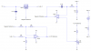
The regulator has the big advantage of being short-circuit and over temperature protected. The transistor has neither.
 
Transistors also need a lot more drive current.
 
Ah I see, cheers for explaining that.

Regarding using the el'cheapo voltage reference: What startup and shutdown conditions would that cause ? Would it cause any overshoot at startup and shut down ? I can see how it would work well when everything is in it's stable state but I'm unsure about other states - I also want to be able to use this on laser diodes which are very delicate.

Is there any reason that I'm missing why I couldn't use 10K resistors instead of the 100K resistors ? I have lots of 10K's ...
 
The shut down just protects the regulator from getting damaged and only happens if it overheats.

You could easilly use 10k resistors, it doesn't matter as long as they're all the same value.
 
Thanks to all of your help, I now have my final circuit. I'll order the parts soon and build it on stripboard.

I may switch the 82K resistor with a 22-turn 100K potentiometer in order to get the maximum out of this. (With the 82K it will be limited to about 1.35A.)

Thanks again for your help guys. :)
 

Attachments

  • High Power Adjustable Current Regulator.png
    High Power Adjustable Current Regulator.png
    19.7 KB · Views: 348
There's no reason why you can't do that.
 
Hi folks,

I'm building something similar to this only using 3x 1084's in parallel. In the last example attachment I see the 1.25v reference. Is this connected to a 1.25v reference IC not in the schematic, or is it just a labeling of one net and they are to be connected together?

Thanks.
 
It's just a label and they are all connected together.

The generation of the 1.25V reference voltage relies on the fact that the LM317 will always try and keep the difference between its output and its reference input as 1.25V.
 
Ok, so I can remove this 1.25v reference I have thats stopping this thing from working!

Did you complete yours? Working ok?

I've got 15V in and 9.3V at 4.5A out, with a pot for max current and a pot for 0 - 100% of that max current.
 
I never got a chance to build mine, ordered the parts just didn't have the time to put it all together. Will do when I get the chance though.
 
Well I don't mean to sound cocky but you can do it with one transistor, 1 resistor and 1 pot;

Code:
+12v  ------>|-------,
(unreg)     LED      |
                     |
                     |
+5v  --------,       |
             |       |
             |       |  NPN (or Darl)
   500 ohm   R       C  TIP122 etc
      pot    R<----B    
             R       E
             |       |
             |       |
             |     Rload  4.7 ohms 5w
             |       |    (etc)
             |       |
Gnd ---------*-------*--

This is a constant-current dummy load, adjustable with the pot from 0A to about 1A, depending if you use 3.9 ohm or 4.7 ohm for Rload.

It will drift 1 or 2 percent as the transistor warms up, which is rarely an issue.
 

Attachments

  • dummy.jpg
    dummy.jpg
    49.3 KB · Views: 609
I would use a switching regulator for this, it seems silly to buy expensive efficient LEDs, then waste a load of power in a linear regulator.
 
Status
Not open for further replies.

Latest threads

New Articles From Microcontroller Tips

Back
Top