Continue to Site

Welcome to our site!

Electro Tech is an online community (with over 170,000 members) who enjoy talking about and building electronic circuits, projects and gadgets. To participate you need to register. Registration is free. Click here to register now.

  • Welcome to our site! Electro Tech is an online community (with over 170,000 members) who enjoy talking about and building electronic circuits, projects and gadgets. To participate you need to register. Registration is free. Click here to register now.

High Frequency Variable Oscillator

Status
Not open for further replies.

nos_slived

New Member
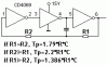
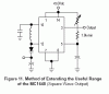
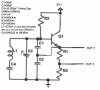
Hey, I'm attempting to build a high frequency variable oscillator on a range of 18 MHz to 48 MHz(preferably 48, but 42 would work if 48 is too high) using the 4011 quad NAND. I want it to work on the circuit that I'm posting, and I just need the values for C1, R1(pot), and R2(pot). Id like it if only one of the resistors was a Potentiometer, but if it cant cover the entire range, I would use 2. Can anybody help me out?
 

Attachments

  • ledflx_264.jpg
    ledflx_264.jpg
    15.9 KB · Views: 1,735
I mean, this cct can work up to 10..15MHz only. For higher frequencies build one with BJT or FET.
 
Sebi,
How did you make a 4011 oscillator go so high? With only 27pF and both resistors 1K with a 12V supply mine barely reached 2MHz.
I have heard that a 4049 high current buffer can reach 6MHz without the input resistor.

Do I dare try using a 74HC00 high-speed Cmos IC for 15MHz or do you think it might melt?
 
Anybody have a circuit that could reach that range?

Or even if I could hit 1MHz-5MHz, and multiply by 12. Anybody have any ideas?

All I have to do is stay under $10(preferably $5).
 
This cct can work safely on 10MHz, but need 15V supply. Some good pieces work up to 15MHz. I strongly recommend the MC1648 for wideband tuning.
 

Attachments

  • osc_181.gif
    osc_181.gif
    2.5 KB · Views: 1,369
  • 1648.gif
    1648.gif
    4.5 KB · Views: 1,415
With C3=250Pf, the frequency is 20 mHz. With C3=10pF, the frequency is 45 mHz. A tuning capacitor from an AM radio would probably have that range.
 

Attachments

  • osc_194.jpg
    osc_194.jpg
    114.4 KB · Views: 1,436
V1 is the 5 volt power supply but supply voltage is not critical. L1 is 7 turns #20 enameled wire on a 1/4 inch form (a standard pencil will do). The turns should be close and don't forget that the leads are part of the inductor, so keep them short.
 
OK.

Thanks. I have changed the pic a bit. Would this still work? Also, what is the difference between the 2 outputs? Could Q1 be substituted for any other transistor? Why does L1 say 275nH (what does it mean)? Did I mention, "Thank You"?
 

Attachments

  • osc_194.2.jpg
    osc_194.2.jpg
    45 KB · Views: 1,219
I had used this circuit as a crystal checker (substitute the crystal for L1, C3 & C4). Out_2 was a 50 ohm drive to my frequency counter. 275 nano-henries is 275*10^-9 henries. Any transistor with Ft greater than 100 mHz should work, eg: 2N3904.
 
OK.

Thanks again.

Does anybody know a cheap circuit that I can add on to one of the outputs to compare that clock to an existing one and light an LED when they are the same?
 
Please don't let this fade to the land of unread threads.

I need this circuit before Friday so I can test it and finish my NES overclocking guide.
 
Status
Not open for further replies.

Latest threads

Back
Top