Continue to Site

Welcome to our site!

Electro Tech is an online community (with over 170,000 members) who enjoy talking about and building electronic circuits, projects and gadgets. To participate you need to register. Registration is free. Click here to register now.

  • Welcome to our site! Electro Tech is an online community (with over 170,000 members) who enjoy talking about and building electronic circuits, projects and gadgets. To participate you need to register. Registration is free. Click here to register now.

hi im new and stuck

Status
Not open for further replies.

karlb123

New Member
Hi everyone, I am a newby

I studied electronics at GCSE and A-Level but didnt really remember to much theoretical stuff and now I have a problem I am sure I can overcome with some help!

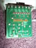
I have a set of LED christmas lights that run on UK Mains voltage (not transformered) and they have a flasher unit on but I want to 'by-pass' this and make the set fully static.

Here is photos of the board:

**broken link removed**

The input wires are on the top left hand corner.

**broken link removed**

I hope you can help me!

Many thanks

Karl Beetson
 
Last edited:
would it work if I:

connect jumpers between the transistor leads closest to the end of the board. This can be done with a single wire that connects straight across those 8 pads in a row.
 
I do not know how expensive this set is, or what kind of loss it would be for you if they were damaged...Common sense, or at least common electronic sense, tells me that two of your wires are your LINE and Neutral inputs, while the other 5 sets of wires represents 4 branches with a common return...THUS 4 transistors individually switchig those branches.

I would certainly think, judging by the two rows of solder points for the 4 transistors, that the bottom row on the picture is either the base or gate, and the other row of 8 solder points are the e-c or s-d junctions. Each base/gate is connected to the IC that is driving them.

You certainly will be turning them on full if you jumper the e-c or s-d junctions (not sure if these or bjts or fets)...which will swicth the lights on.

It appears to me that your line voltage is being rectified by the diode bridge to drive the IC, and the LEDs with no regulation and minimal filtering. I haven't reversed engineered the circuit but you should probably ceck the voltage from common to each transistor leg, measure the voltage drop across the junction and the supply voltage, just to be sure that voltage drop doesn't need to be accounted for, imho.

I would jumper 'em just for kicks and not worry about smoke, if it were me :)
 
hey thanks for your reply,

I am noway confident enough to be probing with a multimeter as its such a high voltage 240v....dont want to electrocute myself.

So do you feel confident that if I solder as in the new attached picture that it will be static and also safe...I dont want any electrical fires etc
 

Attachments

  • 100_2268.jpg
    100_2268.jpg
    65.3 KB · Views: 863
If they were designed to flash causing them to be steady on all the time may likely destroy them, the unit, or your house... Buy a proper unit.
 
Its a MULTI FUNCTION flasher unit. 1 of the functions is static.... but everytime you power off it doesnt remember the last setting used and I wont have access to the push button to go change it...

So if the set can go static whats the difference of "hot-wiring" it?
 
hey thanks for your reply,

I am noway confident enough to be probing with a multimeter as its such a high voltage 240v....dont want to electrocute myself.

So do you feel confident that if I solder as in the new attached picture that it will be static and also safe...I dont want any electrical fires etc


Yes, I do believe a wire soldered straight across all the emitter and collector pins will have the LEDs full on.

And if the unit originally had a full on mode, I see no problem.

But the advice given by the other poster is sage when you consider how much a set of Christmas lights really cost vs a burned down home. Just depends on how confident YOU are with doing it. I wouldn't worry myself, if that means anything.
 
Bridging the transistors will probably work but there may be a problem if the LEDs are multiplexed. A better solution would be to solder a resistor between C and E to limit the current. Without knowing more about the circuit it is hard to make a good guess at a value.

Mike.
 
Depends on how the string is wired, bypassing the transistors is going to give you an extra .6 volts to the LED chains. Also since there's no way to tell as I'm assuming that little vertical board is blobbed IC, it may have been PWM'ing the LED's even when it was in it's static appearing state. There doesn't appear to be any resistors in line with the LED's, something must be regulating the current, if not then it's really a horribly designed circuit.

Just trying to understand the circuit more, you said this was powered directly by mains? Cause what you have there is a simple bridge rectifier with a capacitor filter. That would mean that the blobbed IC is dropping the voltage and must have current limit resistors for the transistor bases? One of those resistors is connected to the IC, and I can't tell what the other one is for. All I can say is go ahead and short the transistors out of the picture and cross your fingers. I sure hope there's an inline fuse on the power cable.
 
The "transistors" are SCRs', if it matters.

Well, I certainly am feeling guilty for not looking up the datasheet. In his first post he called them transistors and I made an ass-umption without bothering to look them up.

I am not good at looking at photographs and reverse engineering, only the "obvious" things. I see that line voltage is being rectified here for the control circuit, but I would be curious to know if the voltage the devices are switching is AC or DC.

If the SCRs are rectifying when they switch it might be a problem.

And if he jumpers them, well who knows if the circuit will operate properly or draw an acceptable current. I wouldn't want to guess.

Was just trying to help and made wrong assumptions. I hope he reads this before potentially destroying his lights.
 
karlb123,

Sorry I didn't post this earlier on TUES - I meant to, but forgot as I burned the midnight oil out late night.

What kind of control chip (IC) is mounted on that 2008L (803) mini PC thru board that drives the gates of those 4 switched (UTC?) PCR406J SCR's?

You really need to post another pix of the component side of the PCB only from the opposite direction.

I would have thought that the mfr would have given you that Strobed option on the PCB, but I see it's only an ON/OFF only scheme with the switch on the GRD side. Kinda weird, but I guess it saves on the micro-switch contacts arcing! I guess if you wanting just straight ON/OFF LED lights then you would just buy them that way.

Shorting out an SCR, or any similar device is NOT highly recommended at all. It only results in SMOKE & FIRE!!

Those PCR406J SCR's btw follow from left to right K-A K-A K-A K-A. Not sure what the J designation is for, but my guess is that it has something to with European standards possibly??

Hope to see another pix from the other side of that 2008L (803) mini PC thru board.

Frank
 
This one's particularly dangerous

Sorry to be a killjoy, but modifying this unit is not a good idea unless you like risking fire and shock. In theory, such a mod could work, but the unit is already dangerous.

I've got a couple of these LED chains with flasher control units off eBay, and they're all unsafe. Similar ones have been banned in the EU and recalled, mainly because they are a fire and electric shock hazard. Definitely don't leave them unattended, and keep children, pets, and anything flammable (e.g. your house) away from them.

The wires attached to the contacts have too small a cross-section (0.11mm²) for carrying mains (the two contacts at the left of the pic above) or a measured 208V DC, which is the maximum output on each of the 4 lines (the one on the extreme right of the picture is the common line). The same type of wire is used for both mains and DC feeds.

The wire also has no resistance to being stretched and broken, so you can end up with live wires pulled out of the flasher if a child or pet treads on the mains lead. Cable strain relief is provided by glueing the wires into the flasher control box, but one gentle pull broke the mains wire outside the box, and left live strands easily accessible.

I replaced the mains lead with proper 2-core mains flex for safety, so I could test it. The feeds to the led chains (25 LEDs per chain) are PWM - the power is rapidly switched off and on, being left on for a longer period when the LEDs need to appear at their brightest. Bypassing the switching PCR406s will only add to the risk of shock, so I'd recommend chucking the flasher unit into a dustbin. Keep the LEDs for another project (with a lower voltage feed - not mains).

You would be better off going to a reputable high-street seller, paying a few quid extra, and getting a non-flashing set of lights which you can use for several years without injuring anyone or starting a fire.

Hope this helps.
 
Status
Not open for further replies.

Latest threads

New Articles From Microcontroller Tips

Back
Top