Continue to Site

Welcome to our site!

Electro Tech is an online community (with over 170,000 members) who enjoy talking about and building electronic circuits, projects and gadgets. To participate you need to register. Registration is free. Click here to register now.

  • Welcome to our site! Electro Tech is an online community (with over 170,000 members) who enjoy talking about and building electronic circuits, projects and gadgets. To participate you need to register. Registration is free. Click here to register now.

Hi and alternative mosfet help

Status
Not open for further replies.
Firstly, hi I'm mike. New to electronics but not electrics and looking for some assistance.
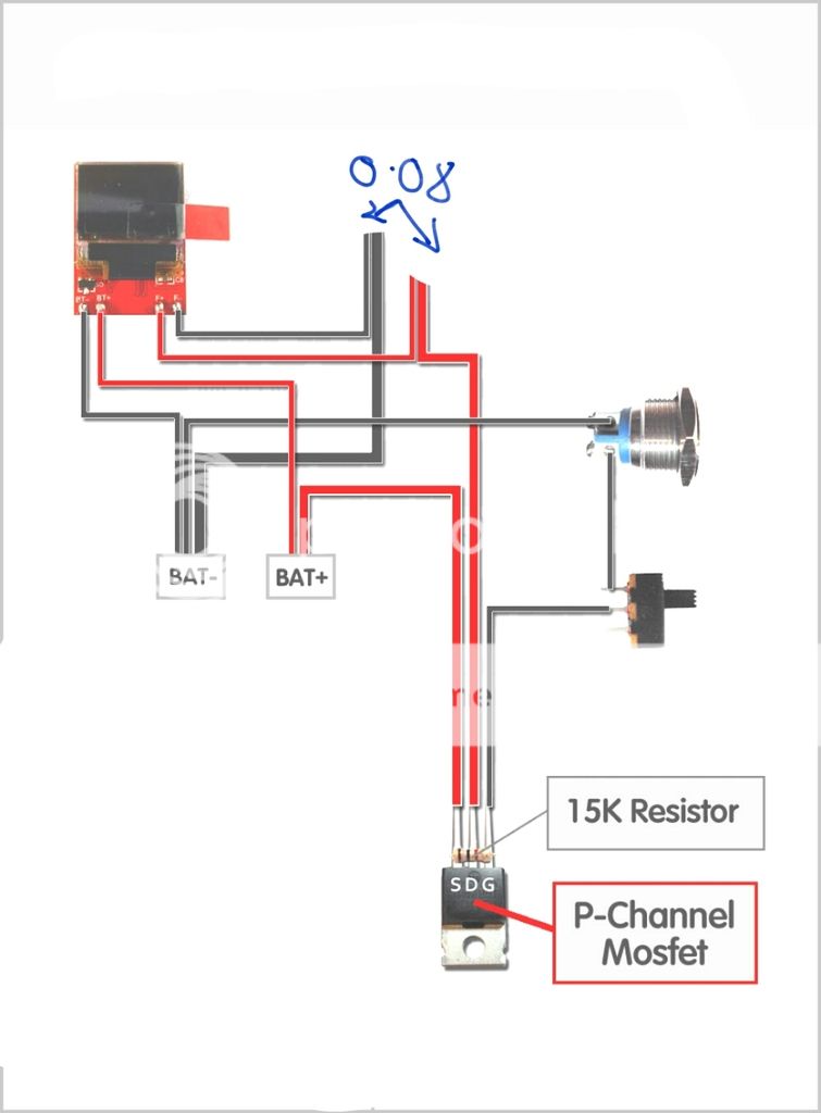
I'm mid way through a project and I've hit a snag.. I have a mosfet (P-Channel Mosfet 30V/80A IPP80P03P4L-04) but under advisement it may not be capable of sustaining the amps I intend.
I've no clue what to put in a Google search to even look for somthing suitable.:sorry:
So.. would any of you kind folk know the highest sustainable amp output p channel mosfet that has similar characteristics to the one I have, and also where to get a few in the UK?

Any help would be much appreciated.
Cheers. Mike
 
It would help to know What Project or specific application?

The Amp Rating is usually OK, IF you put it on a Suitable Size Heat Sink, and If it Stays fairly Cool.
(Amp Rating Goes LOWER with Increased Temperature.)

Sorry Not sure where to buy it in the UK.
Possibly get some from China on EBAY.
Usually Free Shipping But SLOW Delivery Times.

I have lots of STP80PF55, so rated 80 Amps and 55 Volts. (Not Bought from China)
They Cost me $2.35 each in Canadian money, but to send them to you from Canada is not cheap shipping.
 
I'm making a very high power device to run a thermal resistor. It'll be as basic as my electronics understanding lol. But that's all it need be.

5800mah 60c - 90c 3.7v (4.2max) lipo battery, 0.8ohm kanthal thermal resistor, switch and mosfet(with 15k switch resistor) There's a small digital readout that'll also be part of the circuit but only as an amp, volt, watt, ohm level measure.
There's no place for a heat sink unfortunately, itll have ambient airflow but nothing more.

Although I could alter the resistance to accommodate the fet's output, I'd rather not have that as an issue.

Ultimately I want to ring the maximum power from the cell through my resistor the simplest way possible, with the proviso that my digital display works. I'm only here as I was warned that I could exceed my mosfet's capability with the set up I'm planning there. The fet I have was a recommendation. If I'm honest I don't know how to calculate for what I do need, or even if it exists.

I don't mind buying from abroad tbh, I'd just like to percur what I need as quickly as I can.

ronsimpson. Thanks buddy, one of those peaked my interest.. but im lacking enough knowledge to know if the gate voltage suits my needs.
chemelec. Very kind offer.. though I'd not ask it of you. I have a friend in Canada, we swap items regularly and he pays more than double for shipping than I do!!
 
Last edited:
You have a battery. 3.7V with a max voltage of 4.2Volts. Resistor 0.8 ohms. That only 5.25 amps max.
------------------
Can you build the circuit up side down and use a N-MOSFET? I can get more and better parts. (MOSFET-Source on ground and load resistor on the (+) of the battery)

One of the MOSFETs has a 0.004,2 ohm on resistance (if the Gate to Source voltage is 10 volts) So with a load of 0.8 ohms and a MOSFET of 0.0042 ohms. That means you will loose about 0.5% of the power in the MOSFET. There will be about 0.02 volts loss. The part will not be hot! You can use a smaller part!

I think you only have about 3 volts to drive the gate of the MOSFET. That is not good. Looking at the SUM110P04-04L, you need 4.5 volts min. 5 volts is better.
Look for a "logic level" part.
 
Just picking a part at random.
N-MOSFET, turns on with lower gate to source voltage and 0.0025ohms.
upload_2016-6-23_18-29-0.png
 
20160624_015738_zpscv3oiwzd.jpg

^That's as close as i can find to a diagram of what I'm aiming to do..

Sorry, I meant ~0.08ohms, my bad. It's over 220w I believe.. I was given the heads up that my fet could overheat and to look for one that had a higher sustained amp capability. Though given your reply I think I may have been mislead?

The digital readout can only operate with a p channel.

If the fet I have is adequate I'll run with it, if theres a more efficient one I'll jump on that one for sure!.
Because I've never been particularly involved with electronics I've been led and followed the crowd somewhat, though with little practical knowledge of the subject and keen motivation to make what I want there's an element of having to follow what others have said, and also learn not all advice is good advice!

On a side note, and just to satisfy my curiosity.. with regard to the resistance of the fet issue you mentioned, would two fets in parallel be beneficial?
 
Last edited:
You have a battery. 3.7V with a max voltage of 4.2Volts. Resistor 0.08 ohms. That only 52.5 amps max. Yes about 200 watts.

The digital readout can only operate with a p channel.
What is the "digital readout". part number? I don't see it in the picture.

The gate source voltage is only going to be the battery voltage. I think you will run the load until the battery equals 3.0V. So you need a MOSFET that is turned on real good at 3.0V.

Yes you will need a heat sink because you are loosing 5 watts in the MOSFET if it is turned on well.
 
5800mah 60c - 90c 3.7v (4.2max) lipo battery
Is this right?
5.8aH and you are going to pull 50a. The battery will not last long.
What battery? Part number?
-----edited-----
Just looked up a 5800mah battery and it has 0.013 ohms internal. (not the same battery)
So the battery will heat up and not be happy.
 
Last edited:
The maximum collector current and maximum power rating of a transistor, bipolar junction transistor (BJT), MOSFET, Insulated gate junction Transistor (IGBT), are not the main controlling factors.

There are four main controlling factors: maximum voltage, drain source, maximum junction temperature, 150 deg C or 175 deg C depending on manufacturer, and thermal resistance junction to case. The other main controlling parameter is the safe operating area (SOA) of the device.

The most difficult parameter in your circuit is the requirement to turn the PMOSFET fully on with a gate source voltage of 3V (the advised minimum discharge for LIIon batteries). Apart from that there are literally hundreds of PMOSFETs and NMOSFETs that will do your job but, as the other members have said, whatever device is used, never mind how much current and power is stated on the data sheet, it will need adequate heatsinking.

If you want, I will recommend a suitable PMOSFET and do the calculations to define a suitable heatsink.

spec
 
Last edited:
GWI, do you agree that this is the topology that you want (don't worry about the circuit details for the moment)

spec

THIS SCHEMATIC OBSOLETE- REPLACED BY SCHEMATIC OF POST#35

2016_06_24_iss01_ETO_MOSFET_SWITCH_ver1.png

NOTES
(1) R2 is a gate stopper to prevent the PMOSFET from oscillating.
(2) C1 is a ceramic capacitor with an X7R dialectic.
(3) R1 is 1K, rather than 15K, to present the gate of the PMOSFET with a low impedance and also to put more current through the switch to keep the contacts clean.
(4) The nominal terminal voltage of a LiIon battery is 3.6V rather than 3.7V
(5) The star after each component name has no significance
 
Last edited:
If you want, I will recommend a suitable PMOSFET and do the calculations to define a suitable heatsink.

spec

After looking at the math involved I have to say, rather you than me! haha. That would be very kind of you, thanks.

*Just saw your next post.. err.. umm.. err..
I could tell you all about fabricating car components and maybe wiring the headlamps, but I couldn't tell you I know how that circuit works :( if it puts the most power reliably to my heating element and my readout works then yes, that's perfect..
I followed it far enough to assume r3 is my kanthal resistor, s1 my switch. The way the mosfet looks alien to me but that's no surprise, I'm used to seeing the actual wires etc.
If that's, in your professional opinion, an efficient circuit I'd be more than happy to use it. You wouldn't happen to have the part numbers of the components would you?
 
Choice of PMOSFET

Due to my error about the kanthal resistor value this post needs to be rewritten

The Infinion IPB80P03P4L-04 (TO263 pak or any other pak) will be fine for your circuit and will not require a heatsink provided it has a free flow of air around it.

Take the maximum current as 6A for round figires. With -3V gate voltage the RDss will be 10 miliOhms max so the the forward voltage drop across the PMOSFET will be 6A * 10mR = 60 mili Volts. The power dissipation will thus be 6A * 60 mili volts = 360 mili watts. The thermal resistance junction to case to free air is 62 deg C per watt which means that the thermal gradient will be 360 mili Watts * 62WDC= 22.32 deg C. The maximum junction temperature is 175 deg C so the maximum ambient air temperature is 175 deg C- 22.32 deg C = 152.68 deg C.

In practical terms, assume an ambient temperature of 50 deg C, a good assumption for many equipments, then the junction temperature will be 50 deg C + 22.32 deg C = 72.32 deg C, well within the IPB80P03P4L-04 specification maximum junction temperature of 175 deg C.

The safe operating area graph from the data sheet shows that at 4.1 V (LiIon battery advisable maximum charge voltage) there is absolutely no problem with a drain current of 6A.

Unless I have made some gross error somewhere, the IPB80P03P4L-04 will do your job with ease without any heatsink at all.

spec

IPB80P03P4L-04 data sheet
https://www.infineon.com/dgdl/Infin...n.pdf?fileId=db3a30431ddc9372011e07e95eb827d7
 
Last edited:
After looking at the math involved I have to say, rather you than me! haha. That would be very kind of you, thanks.

*Just saw your next post.. err.. umm.. err..
I could tell you all about fabricating car components and maybe wiring the headlamps, but I couldn't tell you I know how that circuit works :( if it puts the most power reliably to my heating element and my readout works then yes, that's perfect..
I followed it far enough to assume r3 is my kanthal resistor, s1 my switch. The way the mosfet looks alien to me but that's no surprise, I'm used to seeing the actual wires etc.
If that's, in your professional opinion, an efficient circuit I'd be more than happy to use it. You wouldn't happen to have the part numbers of the components would you?

Yes, that is correct. R3 is your kanthal resistor and S1 is your switch. When S1 is open the PMOSFET drain source will be open circuit. When S1 is closed the PMOSFET will be short circuit.

Yes, the circuit in post #12 will put the maximum current into your kanthal resistor.

Yes, that is the circuit that I would recommend.

I will sort out a parts list for you. Do you have a preferred supplier: Mouser, Digikey, RS, Farnell for example?

spec
 
Last edited:
Is this right?
5.8aH and you are going to pull 50a. The battery will not last long.
What battery? Part number?
-----edited-----
Just looked up a 5800mah battery and it has 0.013 ohms internal. (not the same battery)
So the battery will heat up and not be happy.

Just to support Ron. He is correct. You will be asking the battery to supply say 60A max. Even the biggest LiIon battery in an 18650 case will not reliably do much more than 20A, so you would need at least three batteries which would need to be the high current type. At least three batteries in parallel, of the type I have in mind, would be necessary.

Alternatively, if you put three batteries in series and changed the resistor to 240 mili Ohms that would be a much better circuit all around.
Four series batteries and a resistor of 320mili Ohms would be much better. But remember that even this will only give a battery duration of around ten minutes.

Six series connected batteries and a 480 mili Ohm resistor would be my recommendation and would give a battery duration of around 15 minutes. Subject to detailed calculations, a PMOSFET heatsink would probably not be necessary.

spec
 
Last edited:
spec Id like to buy the components in the smallest quantity posible with the fastest shipping times, which ever company fits that bill will be where I'd buy.

Power source will be a 'zippy 60c series' lipo pack, rc plane battery.

I've used Sony vtc4 's parallel in the original circuit, but battery life was awful! Hence the big lipo cell :)
The 18650's worked well enough but I needed more current and better life.. so I re-made the device, along the way I was told the mosfet I was using needed upgrading. Thus I landed here, cap in hand for advice.
All your responses have been exemplary I have to say, given my obvious lack of understanding in the area I almost thought I'd be laughed off.
 
Status
Not open for further replies.

Latest threads

New Articles From Microcontroller Tips

Back
Top