http://www.datasheetcatalog.org/datasheet/on_semiconductor/MC14584B-D.PDF is my IC.
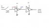
Story: I want to able/disable a signal sent to my device, so a toggle switch is added. To debounce switch, I tried putting a hex schmitt trig invert MC14584B, and my signal goes through schmitt trigger twice. Please Refer to my attachment. My set up has something wrong with it. When started, when switch is off, point A is 5V, point B is 0v, when measured with voltmeter. While voltmeter is still at point B, and I switch the switch off, the volt at point B remains at zero (but didn't jump to 5V on voltmeter). So I put voltmeter at point A, it read 0v. Then I put it at point B again, this time, it read 5V. Why is this happening? Why do I have to place voltmeter probe at point A and next point B, to get the desired reading at point B?
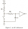
Some other question: Should I place a capacitor load (like as in figure 1 of page 5 of MC14584B data sheet)? What is the capacitor load for?
Story: I want to able/disable a signal sent to my device, so a toggle switch is added. To debounce switch, I tried putting a hex schmitt trig invert MC14584B, and my signal goes through schmitt trigger twice. Please Refer to my attachment. My set up has something wrong with it. When started, when switch is off, point A is 5V, point B is 0v, when measured with voltmeter. While voltmeter is still at point B, and I switch the switch off, the volt at point B remains at zero (but didn't jump to 5V on voltmeter). So I put voltmeter at point A, it read 0v. Then I put it at point B again, this time, it read 5V. Why is this happening? Why do I have to place voltmeter probe at point A and next point B, to get the desired reading at point B?
Some other question: Should I place a capacitor load (like as in figure 1 of page 5 of MC14584B data sheet)? What is the capacitor load for?