Continue to Site

Welcome to our site!

Electro Tech is an online community (with over 170,000 members) who enjoy talking about and building electronic circuits, projects and gadgets. To participate you need to register. Registration is free. Click here to register now.

  • Welcome to our site! Electro Tech is an online community (with over 170,000 members) who enjoy talking about and building electronic circuits, projects and gadgets. To participate you need to register. Registration is free. Click here to register now.

Help with Voltage regulator

Status
Not open for further replies.

AThayer

New Member
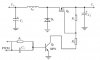
Hey everyone. I'm looking for some help with a voltage regulator design. I have a CNC machine that I am retrofitting. The power supply puts out 85-90 volts dc. I am looking to reduce that voltage to 65-75vdc. The motor drives will draw about 8 amps max. I'm thinking about using a voltage regulator that uses pwm. I would like a very simple circuit. I know a little about Arduino programming so I may use one of those to produce the PWM. I am looking for comments and ideas on how I can reduce this voltage. I see this picture online and was wondering what you thought. Thanks for your help and hope to hear from you soon.
 

Attachments

  • voltage regulator.jpg
    voltage regulator.jpg
    20 KB · Views: 164
Your circuit is not a voltage regulator, instead it is simply a PWM series resistor. Its output voltage will be too high when the load current is low and its output voltage will be too low when the load current is high.
A voltage regulator monitors the output voltage and adjusts it so that the voltage is regulated. Your circuit does not know anything about the output voltage.
 
At any power level, a PWM regulator is more of an intermediate than beginner level project. What is your skill set for assembly and troubleshooting, access to power components, etc? Also, what is your location? No judgement here, just trying to determine the right level of response.

Also, is 65-75 V the actual range a regulator needs to adjust to, or are you saying anything within that range is ok and the output voltage can wander around under load as long as it stays within bounds?

ak
 
My skill level is maybe a little above beginner. The stepper drives will work with a voltage range between 20-80 volts. It also has dip switches that control current. I'm still interested in learning about electronics.
 
Thank you AnalogKid I did a little research and I found a simple non-isolated buck conveter circuit. I was wondering what you thought about it?
upload_2017-1-21_6-52-6.png
 
That is the basic concept that almost all of the controller chips impliment. For regulation, feedback from Vo modulates the duty cycle of the square wave driving the FET switch. Also, for much better efficiency especially at your power level, the diode is replaced by another FET. This is called a synchronous buck.

ak
 
Mr. Analog Post #6: Here is TI.COM version.
This is for 1A but easy to change for 8A.
upload_2017-1-21_7-53-18.png
 
Ok I'm starting to understand that there are IC to control this converter circuit. Could this controller be replaced with a Arduino or even a 555 timer? In the case of the Arduino, software would take care of most right? I'm not trying to be difficult it just seems that the software could replace a lot of components. Also I currently have dc coming from the power supply are these circuits for ac or dc?
 
it just seems that the software could replace a lot of components.
It might replace U1 and most of the components to its left, in the post #9 circuit, but you'd still need the components to the right of U1, plus a level-shifting driver stage. Easier to retain U1 :).
Such control circuits are for DC (though they involve a high frequency oscillator internally).
 
Bigger power MOSFETs, lower resistance and higher power sense resistor, different inductor. One problem with scaling up a design is that a power MOSFET actually is many small MOSFETs inside in parallel, so a larger MOSFET has a much higher gate capacitance. This is why controller chips have a recommended output current range. The chip does not touch the output current directly, but the switching current into a large power MOSFET gate can be several amperes and not all controllers can deliver that.

ak
 
Motors do not care if one side is connect to ground or not.
Here is something I have done before.
The motor is connected from +90V to a point +25V. So the motor sees 65V.
You might use the Arduino to drive the gate. (I would use a "gate driver" to get up to o/12V signal for the MOSFET gate)
For feedback: Divide the 90V and 35V down to (less than 5V). In software (V1-V2=motor voltage)
This is the minimal parts count I can think of.
I did not use Arduino but a UC3843 pwm. (little 8 pin IC) It will current limit and be fine under a short circuit.

upload_2017-1-21_9-31-23.png
 
Ronsimpson can you explain your circuit a little more? This is the kind of circuit I was looking for. Do you have any values for your circuit? Also what pwm ic did you use?
 
Expanding on Ron's suggestion, here's one way you could drive the FET :-
VoltsReducer.PNG
With the component values shown you should get about 65V average across the motor.
 
The system uses stepper motors. The drives that I'm using are leadshine DM860. Will this pwm method work for these drives? Will the drives see 85 volts turning on and off or 65 volts? I think if I was to use a 555 timer I would like to make it variable output.
 
Will this pwm method work for these drives?
Oh, stepper-motors. Possibly not then, if it confuses the stepper-driver electronics.
Will the drives see 85 volts turning on and off or 65 volts?
They'll see 85/90 V switching on/off with this simple circuit.
 
Ok if controlling the output to get what I want is this difficult. Could I control the ac into the transformer using a scr or such and use phase control?
 
Status
Not open for further replies.

Latest threads

New Articles From Microcontroller Tips

Back
Top