;******************************************************************
; *
; Filename: 18F14K22 595 8 Bit LCD Test.asm *
; Author: Mike McLaren, K8LH *
; (C)2012: Micro Application Consultants *
; : All Rights Reserved *
; Date: 11-Jan-2013 *
; *
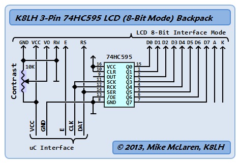
; 18F14K22 + 74HC595 - K8LH LCD 8-Bit Interface Adapter Test *
; *
; *
; *
; MPLab: 8.84 (tabs=8) *
; MPAsm: 5.44 *
; *
;******************************************************************
#include <P18F14K22.inc>
list st=off ; no symbol table in LST file
radix dec
;
; setup configuration fuses
;
CONFIG FOSC = IRC ; Internal RC oscillator
CONFIG PLLEN = OFF ; PLL is under software control
CONFIG PCLKEN = ON ; Primary clock enabled
CONFIG FCMEN = OFF ; Fail-Safe Clock Monitor disabled
CONFIG IESO = OFF ; Oscillator Switchover mode disabled
CONFIG PWRTEN = ON ; PWRT enabled
CONFIG BOREN = SBORDIS ; Brown-out Reset enabled in hardware
; only (SBOREN is disabled)
CONFIG BORV = 22 ; VBOR set to 2.2 V nominal
CONFIG WDTEN = OFF ; WDT control via WDTCON SWDTEN bit
CONFIG WDTPS = 256 ; 1:256
CONFIG HFOFST = OFF ; clock held until HFINTOSC stable
CONFIG MCLRE = ON ; MCLR enabled, RA3 I/O unavailable
CONFIG STVREN = ON ; reset on Stack full or underflow
CONFIG LVP = OFF ; Single-Supply ICSP disabled
CONFIG XINST = OFF ; extended instruction set disabled
CONFIG DEBUG = OFF ; debugger off, RA0 + RA1 available
;--< variables >---------------------------------------------------
temp equ 0x000 ; lcd subroutines
delayhi equ 0x001 ; DelayCy() subsystem var
count equ 0x002 ;
work equ 0x003 ; lcd driver work var
;--< constants >---------------------------------------------------
#define MASK(X) (1<<(X))
brgval equ (16000000/19200/4)-1 ; 19200, BRGH=1, BRG16=1
#define line1 128+0 ; lcd line 1 address
#define line2 128+64 ; lcd line 2 address
;--< defines >-----------------------------------------------------
#define dat LATA,0 ; RA0 -> 595 'ser' pin
#define clk LATA,1 ; RA1 -> 595 'sck' and 'rck' pins
#define ena LATA,2 ; RA2 -> lcd 'e' pin
;
; assembly language helpers
;
#define clrc bcf STATUS,C
#define setc bsf STATUS,C
#define skpc btfss STATUS,C
#define skpnc btfsc STATUS,C
;==================================================================
; K8LH DelayCy() subsystem macro generates four instructions =
;==================================================================
radix dec
clock equ 16 ; 4, 8, 12, 16, 20 (MHz), etc.
usecs equ clock/4 ; cycles/microsecond multiplier
msecs equ clock/4*1000 ; cycles/millisecond multiplier
DelayCy macro delay ; 11..327690 cycle range
movlw high((delay-11)/5)+1
movwf delayhi
movlw low ((delay-11)/5)
call uDelay-(((delay-11)%5)*2)
endm
;******************************************************************
; reset vector *
;******************************************************************
org 0x0000
vreset
goto init ; |
;******************************************************************
; interrupt vector hi *
;******************************************************************
org 0x0008
vinthi
;******************************************************************
; interrupt vector lo *
;******************************************************************
org 0x0018
vintlo
;******************************************************************
; main init *
;******************************************************************
init
clrf ANSEL ; |
clrf ANSELH ; |
clrf TRISA ; |
clrf TRISB ; |
clrf TRISC ; |
clrf PORTA ; |
clrf PORTB ; |
clrf PORTC ; |
;
; setup INTOSC for 16 MHz
;
; movlw 1<<PLLEN ; 4xPLL 'on' for 64 MHz |
; movwf OSCTUNE ; |
movlw b'01110010' ; 16 MHz |
movwf OSCCON ; |
;
; configure EUSART for 19200 baud operation (16 MHz clock)
;
movlw low(brgval) ; |
movwf SPBRG ; |
movlw high(brgval) ; |
movwf SPBRGH ; |
movlw 1<<BRG16 ; |
movwf BAUDCON ; BRG16=1 |
movlw 1<<TXEN|1<<BRGH ; |
movwf TXSTA ; TXEN=1, BRGH=1, SYNC=0 |
movlw 1<<SPEN|1<<CREN ; |
movwf RCSTA ; SPEN=1, CREN=1 |
;
; initialize LCD (8-bit interface mode). please note this is
; not the Hitachi "initialize by instruction" procedure.
;
DelayCy(50*msecs) ; lcd 50 msec 'power up' reset |
movlw 0x38 ; 8-bit, 2-lines, 5x7 font |
call PutCmd ; send "function set" command |
movlw 0x01 ; clear display (1.53-msecs) |
call PutCmd ; send "entry mode set" command |
DelayCy(1530*usecs) ; 1.53 msec delay for "clear" |
movlw 0x06 ; cursor inc, shift off |
call PutCmd ; send "entry mode set" command |
movlw 0x0C ; display on, cursor & blink off |
call PutCmd ; send "display on/off" command |
;
; display "hello" starting at fifth column on line 2
;
movlw line2+4 ; line 2, tab 4 |
call PutCmd ; move lcd cursor to x,y = 4,1 |
movlw 'h' ; |
call PutDat ; |
movlw 'e' ; |
call PutDat ; |
movlw 'l' ; |
call PutDat ; |
movlw 'l' ; |
call PutDat ; |
movlw 'o' ; |
call PutDat ; |
;******************************************************************
; main loop *
;******************************************************************
loop
bra loop ; loop forever |
;******************************************************************
; K8LH "74HC595 LCD 8-bit Interface Mode" Low Level Driver *
;******************************************************************
PutDat
setc ; flag rs = 1 (data) |
skpc ; skip unconditionally |
PutCmd
clrc ; flag rs = 0 (command) |
movwf work ; save byte in 'work' var |
movlw 8 ; use wreg as bit counter |
bitlp
bcf dat ; dat = 0 |
btfsc work,7 ; is it '0'? yes, skip, else |
bsf dat ; dat = 1 |
bsf clk ; clk = 1, clock out a bit |
bcf clk ; clk = 0 |
rlncf work,F ; shift 'work' byte |
decfsz WREG,F ; all 8 bits? yes, skip, else |
bra bitlp ; branch (send another bit) |
bcf dat ; dat = 0 |
skpnc ; rs = 0? yes, skip, else |
bsf dat ; dat = 1 |
bsf clk ; clk = 1, clock out 'RS' bit |
bcf clk ; clk = 0 (leave dat = RS) |
bsf ena ; ena = 1, strobe LCD 'E' pin |
bcf ena ; ena = 0 |
DelayCy(50*usecs) ; required lcd inter-write delay |
return ; |
;******************************************************************
; serial subroutines *
;******************************************************************
put232
btfss PIR1,TXIF ; Tx buff empty? yes, skip, else |
bra put232 ; loop |
movwf TXREG ; |
return ; |
get232
btfss PIR1,RCIF ; Rx char avail? yes, skip, else |
bra get232 ; loop |
movf RCREG,W ; |
return ; |
;******************************************************************
; K8LH DelayCy() 16-bit uDelay (11..327690 cycle) subroutine *
;******************************************************************
nop ; entry for (delay-11)%5 == 4 |
nop ; entry for (delay-11)%5 == 3 |
nop ; entry for (delay-11)%5 == 2 |
nop ; entry for (delay-11)%5 == 1 |
uDelay addlw -1 ; subtract 5 cycle loop time |
skpc ; borrow? no, skip, else |
decfsz delayhi,F ; done? yes, skip, else |
bra uDelay ; do another loop |
return ; return with C = Z = 0 |
;******************************************************************
end

")
")