AGCB
Member
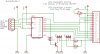
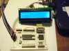
I'm trying to make a portable serial LCD module that I can easily hook up to any project
or PIC with just a few wires using a 74HC595 shift register.
I have used parallel LCDs so I know the basics of the routines. But I can not get this
to work. It assembles fine but the LCD won't initialize.
To give credit where due, my modified routines and hardware use parts and peices from
Nigel, Mike Predko, Blueteeth and probably others that I can't think of right now.
I wanted to try and do the code myself but now I believe it's time to ask for help.
Is there any obvious mistake in this code? I added longer delays to see if the LCD was
being hurried. Thanks. Aaron
Code:
; Send data to LCD via 74HC595
; Modified by Aaron
; This Code Sends the data to the LCD in 4 Bit mode
;
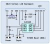
; The data is shifted out to a 74HC595 The QD (Pin 3)goes to the
; LCD's "RS" Bit. Pins QE-QH (pins 4,5,6 & 7) go to the LCD pins D4 - D7
; The LCD E pin is tied to the RCLK latch (pin 12)
; Pins 8 & 13 of the 595 are grounded
; Pins 16 Vcc and 10 SRCLR are tied to 5 v
;
; Hardware Notes:
; PWRT is Enabled.
; The PIC is a 18F1220 Running at 4 MHz.
; PortA.0 is the Data Bit
; PortA.1 is the Clock Bit
list p=18F1220 ;select device in configuration tab
#include <p18F1220.inc> ; Runs at 4 MHz
radix dec
; Register Usage
CBLOCK 0x00C
ENDC
;---------------------------- Define Inforation-----------------------------------
#DEFINE SData PORTA,0
#DEFINE Clock PORTA, 1
#DEFINE STROBE PORTA,2
;------------------ Macros---------------------------------------------
Clkstrobe MACRO ; Strobe the Data Bit
bsf Clock
bcf Clock
ENDM
EStrobe MACRO ; Strobe the "E" Bit
bsf Strobe
bcf Strobe
ENDM
;------------------------------------------------------------------------------
config osc = intio2, fscm = off, ieso = off ;1h
config pwrt = on, bor = on, borv = 27 ;2L
config wdtps = 1, wdt = off ;2h
;mclr enabled (default) ;3h
config stvr = off, lvp = off, debug = off ;4L
;default code protection off ;5L, 5h
;default write protection off ;6L, 6h
;default table read protection off ;7L, 7h
;----------------------------------------------------------------------------
org 0x0000
movlw 0x60 ;internal osc 4.0 MHz
movwf osccon ; pg 17
bcf adcon0,ADON ;turn off AD pg 155
setf adcon1 ;digital I/O pg 156
clrf trisa
clrf trisb ;all outputs
clrf latb ;
clrf portb ;all pins low
clrf porta
movlb 0x01 ;work in bank 1 GPRs
;----END OF BASIC INIT---------------------------------------------
;------------MAIN---------------------------------------------------
call SR_LCD_INIT
circle goto circle
;------------SUBS------------------------------------------------
SR_LCD_INIT
call del_1S
movlw 0x30 ;set 8 bit mode 1st 0011 0000
call LCD_CMD ;to make sure LCD is ready
movlw 0x20 ;Set 4 bit mode 0010 0000
call LCD_Cmd
movlw 0x28 ;function set 0010 1000
call LCD_Cmd ;4 bit, 2 line, 5x7
movlw 0x06 ;Set display character entry mode 0000 0110
call LCD_Cmd ;increment, display shift off
movlw 0x0c ;Set display on and cursor off command
call LCD_Cmd ;,
call LCD_Clr ;clear display
retlw 0x00
; ------command set routine-----------------------------------------------
cblock
templcd
sendreg
endc
LCD_Cmd movwf templcd
swapf templcd,w ;send upper nibble
andlw 0x0f ;clear upper 4 bits of W
call ser_out
EStrobe ;Pulse the E line high
call ms10
movf templcd,w ;send lower nibble
andlw 0x0f ;clear upper 4 bits of W
call ser_out
EStrobe ;Pulse the E line high
call ms10
retlw 0x00
;------------------------------------------------------------
ser_out movwf sendreg ;save copy of number
movlw 0x08 ;init 8 counter
movwf count
testbit bcf SData ;this is the data bit '0' will be sent unless the next instruction
; determines that a '1' should be sent instead
btfsc sendreg,7 ;is the MSb of sendreg '0' or '1'
bsf SData ;it's a '1' so set data bit to '1' ;if not '1' then send '0'
Clkstrobe ;clock it into 595 and shift register to next bit position
call ms10
rlcf sendreg,f ;move to the next bit
decfsz count,f ;decrement bit counter
goto testbit ;if bit counter is not zero goto next bit
return ;done
;----------send character------------------------------------------------
LCD_CharD addlw 0x30
LCD_Char movwf templcd
swapf templcd,w ;send upper nibble
andlw 0x0f ;clear upper 4 bits of W
IORLW b'00010000' ;set the RS bit to data
call ser_out
EStrobe ;Pulse the E line high
movf templcd,w ;send lower nibble
andlw 0x0f ;clear upper 4 bits of W
IORLW b'00010000' ;set the RS bit to data
call ser_out
EStrobe ;Pulse the E line high
call Del_256
retlw 0x00
;-----placement of 1st character---------------------------------
LCD_Line1 movlw 0x80 ;move to 1st row, first column
call LCD_Cmd
retlw 0x00
LCD_Line2 movlw 0xc0 ;move to 2nd row, first column
call LCD_Cmd
retlw 0x00
LCD_Line1W addlw 0x80 ;move to 1st row, column W
call LCD_Cmd
retlw 0x00
LCD_Line2W addlw 0xc0 ;move to 2nd row, column W
call LCD_Cmd
retlw 0x00
;----Basic house keeping---------------------------------------
LCD_CurOn movlw 0x0d ;Set display on/off and cursor command
call LCD_Cmd
retlw 0x00
LCD_CurOff movlw 0x0c ;Set display on/off and cursor command
call LCD_Cmd
retlw 0x00
LCD_Clr movlw 0x01 ;Clear display
call LCD_Cmd
retlw 0x00
;------------DELAYS-------------------------------------------
;COMBO of sec and mS and us delays--------------------------
;-------------Adjustable delay-----1-255 seconds (4 1/4 min)
; ;enter with number of seconds in wreg before CALL
;i.e. movlw d'xx'
cblock
bc1
bc2
bc3
dc1
dc2
dc3
secs
endc
adj_delay_sec
bcf intcon,gie ;disable global interrupts
movwf secs
repet call delay_ms
decfsz secs ;1 loop per number entered with in wreg
goto repet ;
bsf intcon,gie ;enable global interrupts
return
delay_ms
movlw d'100' ;
banksel bc3 ; Each loop here takes 1 SECOND
movwf bc3 ;
dly2 movlw .13 ;
movwf bc2 ;
clrf bc1 ;
dly1 decfsz bc1,f ;
goto dly1 ;
decfsz bc2,f ;
goto dly1 ;
decfsz bc3,f ;
goto dly2
return
;------Adjustable delay-----10-2550ms(2.55 seconds)------------
; delay = W x 10ms
; enter with multiplier in WREG before CALL
;i.e. movlw d'xx'
adj_delay_ms
bcf intcon,gie ;disable global interrupts ; delay W x 10ms
banksel dc3 ; Wx10.015ms
movwf dc3
dly2a movlw .13 ; repeat inner loop 13 times
movwf dc2 ; -> 13x(767+3)-1 = 10009 cycles
clrf dc1 ; inner loop = 256x3-1 = 767 cycles
dly1a decfsz dc1,f
goto dly1a
decfsz dc2,f ; end middle loop
goto dly1a
decfsz dc3,f ; end outer loop
goto dly2a
bsf intcon,gie ;enable global interrupts
return
;---uS_delay Range 75uS - 19,375uS (19 mS) ?????????????????????
;enter with <<desired delay devided by 75>> in W ('d' 1 - 255)
;round to nearest whole number
;I.E. desired delay = 750uS ÷ 75 = 10
;I.E. " =5mS = 5000 uS ÷ 75 = 66.66 round to 67
;before CALL instruction ????????????????????
cblock
cya
cyb
cyc
endc
us_delay
movwf cya
movlw .25 ;25 inner loops
movwf cyc
more movf cya,w
movwf cyb
cy1 decfsz cyb
goto cy1
cy2 decfsz cyc
goto more
return
;-------256 uS delay-----------------------
cblock
count
endc
del_256 movlw 0xff
movwf count
repeat decfsz count,f
goto repeat
return
;------------- "canned" common delays in seconds ----------------------
Del_1S movlw .1
rcall ADJ_DELAY_SEC
return
Del_2S movlw .2
rcall ADJ_DELAY_SEC
return
Del_3S movlw .3
rcall ADJ_DELAY_SEC
return
Del_5S movlw .5
rcall ADJ_DELAY_SEC
return
Del_10S movlw .10
rcall ADJ_DELAY_SEC
return
;----Canned MS delays---------------------------------------
;---- 10 millisecond ------------
MS10 movlw .1
call adj_delay_ms
return
;---- 100 millisecond ------------
MS100 movlw .10
call adj_delay_ms
return
;---- 500 millisecond (1/2 second)-------
MS500 movlw .50
call adj_delay_ms
return
end