Continue to Site

Welcome to our site!

Electro Tech is an online community (with over 170,000 members) who enjoy talking about and building electronic circuits, projects and gadgets. To participate you need to register. Registration is free. Click here to register now.

  • Welcome to our site! Electro Tech is an online community (with over 170,000 members) who enjoy talking about and building electronic circuits, projects and gadgets. To participate you need to register. Registration is free. Click here to register now.

Help with Scoreboard...

Status
Not open for further replies.
OK, here's what I have (see attached)
They don't make sense to me.

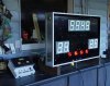
First pic is of the actual board.
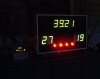
Second pic is of when I breadboarded one segment and DP and logged values (in colors).
Based on those values I made the actual board, etc.
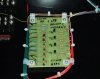
Third pic is of the whole show T1-T4, I did this because the values varied when I would of thought they should be all the same, etc.
So, there ya go.......

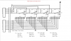
PS-> that base resistor is actually 8K2, not 8K.....
Also, forgot to list Vbe values but they are there on the schematic....
These values obtained with LEDs set at "0000" ('g' segment values would be "0")
 

Attachments

  • P4010623..JPG
    P4010623..JPG
    112.9 KB · Views: 177
  • MPSA64 LED Biasing&.png
    MPSA64 LED Biasing&.png
    136.6 KB · Views: 157
  • MPSA64 LEDs Circui&.png
    MPSA64 LEDs Circui&.png
    133.9 KB · Views: 165
Last edited:
hi,
I guess you measured these values using a voltmeter.?
If so the you have a problem trying to determine the actual voltages because the LEDs are multiplexed.

This means the Velleman PIC switches ON each LED MPS transistor driver in sequence, ie: D1 on, D2 to D4 off, then D2 on and D1,D3,D4 off and so on, then the sequence repeats.
Ideally each LED is only on for 25% of the time, as the scanning sequence is so fast, the eye see's the LED's as all being on.

So when you measure with an ordinary voltmeter you will not see the 'actual' voltages.

The way to read each voltage accurately is use an oscilloscope.
 
hi,
Just done some calculations and simulations on your circuit.

The 120R is allowing 66mA to flow thru the led for a 25% ON duty cycle, so thats approx 16mA average.
You could push it to about 20mA by using 100R on place of the 120R, but it will be a little over the specified limit for the LED.

I would suggest you search for a more efficient LED that will give more lumens/mA.

Man, mamma never told me about all this stuff ! !
OK, lets do this, you have given me a value of 100 ohms for the segment LEDs.
If you would, give me a value for the DP LEDs
and I'll try them and see how they act, etc...
I need to see if I can make do with these LEDs, hate putting out the bucks for new ones and have these collecting dust.
If after all that and they still arn't working well, I guess I'll have to break down and buy some new ones......
I appreciate your help on this thing, nothing was said on the other forum about taking into consideration the average voltage verse the non multiplexing voltage, etc, etc.
Now I'm having to consider Lumens/ma, whew, will be glad when this thing is done....
Tx's so much,
Oxbo
 
Morning oxbo,
The problem with 'mbarazeen's circuit, is that you cannot turn OFF the lower transistors.!

upper transistor (for the particular segment) turns off simultaniously with the lower ones, thats the reason i didnt suggest to use the same arrangement of opto couplers to lower ones.

ericqibbs, do you still think that it will not turn off?
 
upper transistor (for the particular segment) turns off simultaniously with the lower ones, thats the reason i didnt suggest to use the same arrangement of opto couplers to lower ones.

ericqibbs, do you still think that it will not turn off?

hi,
You must consider that all the 4 LED's 'a' segments are connected together as are all the 'b's and so on and the LED anodes are switched on one at a time.

As the lower transistor base in your circuit is connected to 0v or +5V and its emitter is connected to +12V, the transistor is always on.
 
OK;
Replaced the resistors and can see a big improvement.
Measured current of one segment and it reads 23ma, am just going to have to live with it.
The DP's actually look about the same brightness, so am going to say "I'm happy".
And, I think that will wind this problem up and I can finally move on.
If they mess up down the road I certainly know how to deal with them now.
Thank you so much Mr Gibbs, I've learned a great deal, you've solved my headache.
I wish there were more I could do to show my appreciation......
Take care,
Oxbo

hi Oxbo.
Pleased to hear that its working at last.:)

For future displays you should consider using individual LEDs to make the segments.
You could use say 3 high bright leds per segment, your existing circuits would cover it OK.
 
hi,
You must consider that all the 4 LED's 'a' segments are connected together as are all the 'b's and so on and the LED anodes are switched on one at a time.

As the lower transistor base in your circuit is connected to 0v or +5V and its emitter is connected to +12V, the transistor is always on.

its emitter is connected to 12V but not directly, its via the opto coupler. when one segment (7 segment) is energized all other 3 are off and connected LEDs will not get 12V at all.

Edit: i think some thing i didnt mention clearly, that the total number of lower transistors are not 7, instead they are 7x4, each segment would have 7 transistors and bases are wired to a,b... via resistors.
 
Last edited:
OK,
Here's a couple pics of the scoreboard in action.
Everything working perfectly.
Doesn't like the daytime too much, but, just too bad.
Thanks so very much........
 

Attachments

  • P4040629..JPG
    P4040629..JPG
    128.7 KB · Views: 184
  • P4040633..JPG
    P4040633..JPG
    78 KB · Views: 179
OK,
Here's a couple pics of the scoreboard in action.
Everything working perfectly.
Doesn't like the daytime too much, but, just too bad.
Thanks so very much........

hi D,
Looks good.:)
Have you tried placing a sheet of 'green' transparent film in front of the big green LED's?
It should reduce the reflection and also hide the unlit segments.
 
hi D,
Looks good.:)
Have you tried placing a sheet of 'green' transparent film in front of the big green LED's?
It should reduce the reflection and also hide the unlit segments.

Hi Mr Gibbs;
Nope, never heard about green film (will look into it).
I did find a nice piece of flat black foam board that I cut out the LEDs dimensions and it fits/looks good, also got a clear piece of plexiglass for the final front piece.
Just got to get a stand for it now, and get it out of my house ! ! ! ! ! !
Sure hope it works for years to come, I don't relish ever seeing it again.....
Almost a year and a half messing with it, and being dumb as a log, has been a journey....
Have a nice day,
Oxbo
 
Status
Not open for further replies.

Latest threads

New Articles From Microcontroller Tips

Back
Top