Continue to Site

Welcome to our site!

Electro Tech is an online community (with over 170,000 members) who enjoy talking about and building electronic circuits, projects and gadgets. To participate you need to register. Registration is free. Click here to register now.

  • Welcome to our site! Electro Tech is an online community (with over 170,000 members) who enjoy talking about and building electronic circuits, projects and gadgets. To participate you need to register. Registration is free. Click here to register now.

Help with output transistors

Status
Not open for further replies.

trident9

New Member
Please help with design of final output configuration and selection of transistors. Want to minimize Vce(sat) and use TO-92 devices. Maximum continuous power will be 6 watts. I am thinking two TO-92 transistors in parallel can handle 6 Watts without heat sinking. Is the Sziklai configuration overkill?
______
trident
 

Attachments

  • Amp1_sch.png
    Amp1_sch.png
    6.3 KB · Views: 223
Last edited:
The entire thing looks like overkill :D

But use a PNP output transistor to feed the motor, feeding the motor from the collector, the losses are far less than way.

You also can't just parallel output transistors, you MUST use current sharing resistors in the emitters, which would be another source of loss.
 
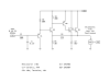
This circuit does not intentionally saturate the output transistors, as the filtering of C2 prevents the output from following the PWM input waveform. This is probably appropriate, since most brushless DC motors get confused by interrupted (PWM) DC.

Your output stage is a power operational amplifier that attempts to match the voltage across the motor to the ((10k+33k)/(10k)) filtered PWM input, which is 0-3V. That means that the motor voltage in this circuit can try to be 0-(4.3*3)V, or 0-12.9V (bounded by the 12V supply). The remainder is dissipated in the two output transistors which are in the linear mode. If the motor is 6W at 12V, this is 500mA. This is greater than twice the collector rating of the 2N3904, so even if they were OK in parallel, two is not enough. And at half output, if the motor needs say 300mA (it's not likely to be linear) this is 1.8W in the transistors. This is much more than double the rating of the transistor. Again, two is not enough.

You need a larger transistor, preferably a single one so you don't have to equalize emitter currents. I suggest any NPN of the TIP series transistors which you can get easily such as TIP31, with a small clip-on heat sink. The TO-220 package can theoretically handle 2W without a heat sink, but it can burn you or your board.

You may need other components on the collector of Q3 to prevent oscillation in the final stage, and unless you trust your PWM to be a stable 0-3V you might want to amplify and square it.
 
Apologies, I did not state my objective well. When the PWM duty cycle is 100%, I want the output to be 11.5 volts or more. Duty cycles of less than 30% are not anticipated as most 12 volt fans will stall below 4 volts. A P-channel MOSFET would be preferable as the output transistor. Devices with suitable specifications abound in SMT packages, however a leaded device is required for this build and I've had no success finding one. So I moved on to a BJT output. Between a PNP Darlington and Sziklai pair, which would allow the the output to swing closer to the 12 volt rail?
______
trident
 
The Sziklai pair can saturate at 0.6V so it beats the PNP Darlington hands down. You just need a beefier output transistor (TIP31 etc) instead of trying to parallel those tiny things.
 
I bread boarded the circuit with parts on-hand subbing a KSD880-Y for the TIP31. With R4: 29.93K, R5: 9.95K, Vcc: 12.03V and 2.99v at base of Q1 the final output is 11.28V @ 109mA. Thanks for the help mneary and Nigel.
______
trident
 

Attachments

  • Amp2_sch.png
    Amp2_sch.png
    6.2 KB · Views: 165
If you want to decrease the top end loss, (like maybe 11.7V instead of 11.28V), you can divide R3, R4, and R5 by a factor of, say, 5. (e.g. 22k, 6.8k, and 2.2k).
 
Thanks for the follow up. If I am understanding correctly, reducing the values of R3, R4, and R5 will increase the drive current of Q4 and Q5, pushing them further into saturation. will that make Q4 and Q5 run hotter? If so think I'll stick with the original values. For a 1500RPM fan, the difference between 11.3V and 11.7V translates to approximately 100RPM which is negligible for my application.
______
trident
 
Last edited:
Thanks for the follow up. If I am understanding correctly, reducing the values of R3, R4, and R5 will increase the drive current of Q4 and Q5, pushing them further into saturation. will that make Q4 and Q5 run hotter? If so think I'll stick with the original values. For a 1500RPM fan, the difference between 11.3V and 11.7V translates to approximately 100RPM which is negligible for my application.

It wouldn't make much difference (if any) to the voltage loss, because you're still feeding the motor from the emitter of a transistor instead of the collector, so you've got 0.7V more drop than you need have (as you've got the EC drop on the driver, plus the BE drop on the output).
 
I stand corrected: I thought the Sziklai pair was better than the Darlington. Re-reading the Wikipedia article on the subject, I understand that they are roughly equivalent in saturation characteristics (except for polarity).
 
Nigel

To get the advantage of a single Vce drop using a PNP for the final output, I'll need to drive it with a power gain stage. Can an emitter follower be used get the required current gain? Is there a better configuration to use?
______
trident
 

Attachments

  • Amp3_sch.png
    Amp3_sch.png
    5.2 KB · Views: 163
Q3 will blow up as there is nothing to limit the collector current. Q4 will probably be damaged too.
 
I really didn't want to work this hard. :eek:

No, I would place the current limit in the base of the TIP32 or in the emitter of the BC327.

I think at this low collector current I expect a typical saturated gain of 20 or better, so I would use about 5 mA base current. The base resistor would be about 1.5k (between 1.2k and 1.8k), 1/8 watt or larger. I would make R6 about 10k (really anything between 10k and 100k).
 
After testing many of the fans in my spares box, it appears the current rating on a brushless fan is the starting current. The actual running current is between 25% and 45% of the rated current depending on the impeller size and bearing construction. From this data, it would be possible to squeak by with two TO-92 transistors in a complementary [Sziklai] or Darlington pair for 3W continuous and 6W starting. Not wishing to test Murphy's Laws, I think the best course would be to use a heat sink.
______
trident
 
The problem with generic brushless fans is that they don't handle back pressure very well, once you put them in a working system if they're loaded wrong their CFM drops like a rock their current goes up and you just lose it all to chaotic useless air cyclones near the blades, no air moves out of the system.

The trend by large and far is to use DC brushless blowers not fans to move air in a PC case and around components, some low pressure industrial situations actually use them as high CFM low pressure compressors because they handle back pressure very well. Box fans (typical PC fans) only work well outside of small enclosures.

**broken link removed**
 
Last edited:
ok.... don't go back to the 3906's..... they're only rated at 360mW each... that gives you 720mW total MAX dissipation it's easier to use a single TO-220 device rather than 10 or more TO-92 devices.

the second thing is that you are using this as a PWM drive for a fan (at least according to the label on your input signal). so what you really want to do is speed control. 25khz is a pretty fast transition from saturation to open circuit for some transistors. you may need to employ some "speedup" techniques on the base of the output device. have you determined whether or not the fan you will be using responds well to pwm control? a lot of these small computer fans have oscillator and driver circuits driving the brushless motor, and may not behave well with pulses for an input voltage. some of them may even have an electrolytic cap to filter the 12V lead, and if it does, the motor might behave as it would with a variable DC source and not start turning until the average voltage gets above 9V or so. just a few things to think about. i've dissected a lot of these fan motors to see what fails mechanically (the bushings wear out on the cheap ones) and see what fails electrically (usually a shorted driver transistor inside or the electrolytic dries out, making the internal circuit so noisy, it interferes with it's own operation).
 
i've always had good luck with stacked fans. i had a PC power supply that i stacked fans on (one original one on the inside, a second one on the outside with the airflow arrows matched) and it ran for 7 or 8 years 24/7. of course you could hear the fans all the way upstairs, but i never had that power supply overheat or had a cap go bad in it. i was running two full height 100Meg Maxtor MFM drives (yes, that was back in the dinosaur days.....) and the power supply lasted through upgrades from the original 286 motherboard to a pentium I/100 motherboard (and probably breathed a little easier when the HDD's were upgraded to 3.5"IDE drives from the 5" MFM drives). i had to finally retire the "jet engine" when somebody gave me parts for a PII machine and the motherboard footprint was too different to use in that case.
 
Status
Not open for further replies.

Latest threads

New Articles From Microcontroller Tips

Back
Top