Continue to Site

Welcome to our site!

Electro Tech is an online community (with over 170,000 members) who enjoy talking about and building electronic circuits, projects and gadgets. To participate you need to register. Registration is free. Click here to register now.

  • Welcome to our site! Electro Tech is an online community (with over 170,000 members) who enjoy talking about and building electronic circuits, projects and gadgets. To participate you need to register. Registration is free. Click here to register now.

Help with MacSpice

Status
Not open for further replies.

1965mt

New Member
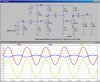
Could someone load this into spice and tell me why the circuit does not behave the same way as the real circuit? i.e. what am I doing wrong? There are two BC183 transistors.

boost
*
vin 1 0 sin(0 .1V 1k)
vcc 10 0 9V

Ri 1 0 100K
C1 1 3 1UF

q1 5 3 4 generic
Rb1 10 3 100K
Rb2 3 0 22K
Rc1 10 5 12K
Re1 4 0 1K

C2 5 6 1UF

q2 8 6 7 generic
Rb3 10 6 50K
Rb4 6 0 22K
Rc2 10 8 3.2K
Re2 7 0 325

C3 8 9 1UF
Ro 9 0 100K
Rload 9 0 100K

.MODEL generic NPN BF=150 VAF=50 IS=1.E-12 RB=100 CJC=.5PF TF=.6NS
.control
* Time domain analysis
tran 5ms 100ms 2ms
plot v(3) v(9) v(6) v(8) v(5)
.endc
.end
 
Well, you didn't say what the difference between your sim and the real circuit is, however, with the parameters in the .Model statement, both q1 and q2 are not biased correctly, and the input is overdriven.

Do .OP solution, and you will find that q1 is saturated (Rb1 is too low, should be ~200K), and to center the voltage swing, q2's bias should be adjusted, too (RB3 should be ~160K).

With the bias problems fixed, the largest input that will not clip is ~70mV.

Ri shunting the input voltage source is redundant. Why are there two load resistors Ro & Rload in parallel?
 

Attachments

  • Draft4.jpg
    Draft4.jpg
    272.1 KB · Views: 600
Mike, Thanks for the response. Those two changes made the difference in the simulation.

The actual output of the circuit that I built was closer to the output in your simulation,,, but using the values that I listed previously. So there are two things going on, I will change the circuit values to the ones you show to see the impact. But, I did have .4V on the emitter and 1V on the base with 4.5V on the collector.
 
I'm guessing that the .Model parameters do not match the actual transistors you are using...
 
Help with Mac Spice

By using the voltage data I calculated the base/collector current and then calculated the hfe. Doing this I get an hfe = 13. When I plug this number into spice the simulated curves match the circuit that I built.

The problem is that the data for the BC183 indicates that the hfe should be a lot higher.
 
Last edited:
Status
Not open for further replies.

Latest threads

New Articles From Microcontroller Tips

Back
Top