Continue to Site

Welcome to our site!

Electro Tech is an online community (with over 170,000 members) who enjoy talking about and building electronic circuits, projects and gadgets. To participate you need to register. Registration is free. Click here to register now.

  • Welcome to our site! Electro Tech is an online community (with over 170,000 members) who enjoy talking about and building electronic circuits, projects and gadgets. To participate you need to register. Registration is free. Click here to register now.

Help with ID???

Status
Not open for further replies.

Nhrafan

New Member
I really need help identifying these components so hopefully I can repair this device.
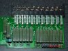
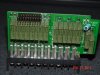
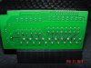
First I will tell you the parts in question are on a board that is part of an output board on a PLC unit.

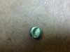
I believe the small green one is a capacitor, although I don't know the values.
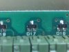
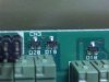
The one I really have a problem with is the small black ones.
I believe they are zener diodes but have no idea if I'm correct or what to replace them with?
If I remember right I connected AC where DC should have been or something like that and pop!
Here are pictures taken with my phone. I can get clearer pictures on anything you need if necessary with a much better camera.
Thanks in advance!
 

Attachments

  • 2011-02-18_18-31-13_342.jpg
    2011-02-18_18-31-13_342.jpg
    653.1 KB · Views: 247
  • 2011-02-18_18-28-08_267.jpg
    2011-02-18_18-28-08_267.jpg
    432.6 KB · Views: 246
  • 2011-02-18_18-27-46_804.jpg
    2011-02-18_18-27-46_804.jpg
    433.1 KB · Views: 227
The cap looks like a 10 uF electrolytic.

The 3 pin devices appear to be diodes, given their D numbers.

I expect there are 2 diodes in each package with either a common anode or common cathode.

Have you used a DMM set to the diode setting to measure them?

Do a search for the number printed on them in the SMD area of a supplier's web site.
 
Thanks!

How should I measure the diodes?
Not sure which is which on these. I do have a good, working, identical card that I can use for measurements if needed, I guess I could measure those and see what I come up with and compare it to ones on the bad card??

Let me know any troubleshooting advice or directions you may have for me with this. I really appreciate the help. I know enough to get me by but have never really repaired anything before, just modify and test some things.

Thanks again.
 
Thanks! You're welcome.

How should I measure the diodes?
Not sure which is which on these. I do have a good, working, identical card that I can use for measurements if needed, I guess I could measure those and see what I come up with and compare it to ones on the bad card??

Let me know any troubleshooting advice or directions you may have for me with this. I really appreciate the help. I know enough to get me by but have never really repaired anything before, just modify and test some things.

Thanks again.
Use your DMM set to continuity/diode option.

If you put the + probe on the anode of a diode and the - probe on its cathode, you should see a reading in millivolts. For a silicon diode it will be about 600. For a Schottky diode it will be about 300 mV.

Then reverse the probes so + goes to the cathode. There should be no reading in this direction as the diode is blocking.

HOWEVER, if you are reading it with the diode soldered onto a PCB, it may give misleading results if there is a parallel path.

Start with a single diode and then do the doubles.

You should be able to determine whether the doubles are common anode or common cathode. However, it is possible that they are in series, ie. anode of one connected to the cathode of the other.

As for fault finding techniques, I posted some guidelines on this for someone recently. I'll find the post and give you link to it after I post this.

Here it is

https://www.electro-tech-online.com...leshoot-a-circuit-without-a-schematic.116280/
 
Last edited:
Here are a few more pictures of what I'm working with here in case anyone has any more suggestions.
I am going to start testing things today and will post results in a few hours.
 

Attachments

  • DSC02107.JPG
    DSC02107.JPG
    1.3 MB · Views: 239
  • DSC02102.JPG
    DSC02102.JPG
    151.8 KB · Views: 222
  • DSC02106.JPG
    DSC02106.JPG
    149.3 KB · Views: 221
Ok, I tested the good board and believe I found that the diodes are common anode.
When I connect red test lead to double side of diode and black lead to opposite side I get a reading of 800. When switched around get a reading of open.

Testing diodes on damaged board results in:

By the way D23 is where the 24V is to be connected and 120V was instead...
 

Attachments

  • Test1.pdf
    281.2 KB · Views: 263
Status
Not open for further replies.

Latest threads

New Articles From Microcontroller Tips

Back
Top