Continue to Site

Welcome to our site!

Electro Tech is an online community (with over 170,000 members) who enjoy talking about and building electronic circuits, projects and gadgets. To participate you need to register. Registration is free. Click here to register now.

  • Welcome to our site! Electro Tech is an online community (with over 170,000 members) who enjoy talking about and building electronic circuits, projects and gadgets. To participate you need to register. Registration is free. Click here to register now.

Help with fan control

Status
Not open for further replies.

trident9

New Member
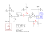
Would like help optimizing this circuit. I want the final output to swing from 5V to the positive rail. The gate resistor (R7) is purposely large to limit the output slew. My question involves the input dividers: R3, R4 and R5, R6. As the impedance of R3, R4 increases, the offset from current into the buffer amp decreases, but at some point the input bias current of the error amp will be an issue. Is 170K a reasonable compromise? Then again, without using a negative bias voltage, is this the best configuration to achieve the 5V to positive rail output swing?
 

Attachments

  • Amp_Bias_LM358_sch.png
    Amp_Bias_LM358_sch.png
    17.3 KB · Views: 233
Last edited:
Where is the PWM coming from?

Why not just use PWM to control the speed of the motor?

You might need some frequency compensation because Q1 is a common source amplfier in the feedback loop of an op-amp and will give more gain and more phase shift, there again, R7 and the gate capacitance is probably already doing that.
 
The PMM originates from a 4-wire fan header on a personal computer motherboard, an open drain output with a maximum pull-up of 3.3 volts that can sink up to 5mA. I am using an after market heat sink on the CPU so the boxed INTEL fan is useless. Also because it is the CPU, I need to insure that the fan will not stall, hence the minimum 5V output requirement.

I want to be able to use the FG signal (tachometer) of the controlled 3-wire brushless fan which is 2 pulses per revolution, pull-down to ground. At low duty cycles the the PWM on time is less than the FG signal on time, so i would need to stretch or average the FG signal to make it usable.

It has also been suggested that I use a PIC. The circuit would be easy to build, but the last time I did any programing it was in FORTRAN, so I would need copious help to write the necessary code.

What I'm looking for is something that has a small physical footprint and can be knocked out on perf-board with out too much fuss. I would be just as happy with a discrete component circuit, but have been unable to find any design information to pursue that type of build.
 
Last edited:
Why are you converting the PWM to constant voltage to power the motor?

Surely it's easier you use some level shifting so the PWM can control the speed of the motor?
 
Are you sure?

What's the minimum voltage?

If the voltage is too low then it won't work anyway.

You could place a small capacitor across the motor leads to stop the voltage from falling too low.
 
Thank you for your input Hero999.
This thread appears to be diverging for my original question. May be I should start a new thread with a subject title that better frames my question.
 
No, don't start a new thread because this one is full of information relivent to your question.
 
What's the minimum voltage?

A 3-wire buushless fan has an open-collector, open-drain output for the FG signal {tachometer}. A pull-up to 12v is on the motherboard. As long as there is sufficient voltage to operate the embedded fan driver ASIC, it's a non issue.

For my application constant voltage is more desirable. The fan motor windings and impeller can behave like the voice coil and diaphragm of a speaker. Direct PWM can create annoying acoustic noise even when the primary frequency is above the range of human hearing.

Can we focus on the original question?

I want to minimize the voltage drop across the voltage follower output without causing excessive error in the output amp input.
 
Last edited:
Do you know what the minimum voltage is?

It doesn't matter which method you use, it'll be a limiting factor.

To ander the orginal question: the drop-out voltage equal to the MOSFET's channel resistance multiplied by the current taken by the fan. If you use a low resistance MOSFET should make the loss negligable. You could use a N-channel logic MOSFET, but you'll need to power the op-amp from a higher voltage than 12V which is a pain but could easily be done with a voltage doubler.
 
Do you know what the minimum voltage is?

It varies, some 3-wire brushless fans will operate satisfactorily with as little as 2.5V, but 5v is appropriate for the fan I'll be using, it stalls at 4.25V.

The FQP27P06 has an Rds of 100m Ohm, maximum continuous fan current would be 12.6V / 60 ohm = 210mA.

Are we talking about the same thing? My question is about the values of R3, R4, R5 and R6.
 

Attachments

  • Amp_Bias_LM358_sch2.png
    Amp_Bias_LM358_sch2.png
    17.5 KB · Views: 170
Last edited:
The attached circuit was used to drive multiple fans from a motherboard. Granted not your goal here but my read is you always want the fan running on a minimum 5 volts regardless of PWM. So what would happen if in the attached circuit the fan (assume a single HSF fan) had a maybe 50 Ohm pot rated for a few watts shunting the MOSFET? The pot adjusted for a good speed less the PWM? Your fan would always run at some minimum speed and when PWM hits the FET it will run at whatever. Then tie your tach return from your fan back to your motherboard. The circuit worked well driving a bunch of fans as it was intended to do so it should work with the FET shunted with a pot unless I am missing something as I haven't given it much thought or tried it.

**broken link removed**

Ron
 
Interesting solution Ron and I don't see any electrical problem, however a 2W pot would likely increase the board area by 50% or more and small physical size is an important goal for this project.
 
It seems like an odd circuit in that I'm pretty sure it can be done using a single op-amp.

Not that, it matters because op-amps invariably come in pairs anyway.
 
Interesting solution Ron and I don't see any electrical problem, however a 2W pot would likely increase the board area by 50% or more and small physical size is an important goal for this project.

Option #2 based on the current draw of the HSF fan with 12 volts applied would be a simple fixed resistor. The idea of the pot was just to come up with something. I think initially I figured like 30 or 35 Ohms give or take.

I am also not sure the MOSFET will like being shunted as I never did it. The circuit I posted was something I came up with for a server application running a bunch of fans and the single PWM signal from the motherboard was not working. The circuit works but I never tried shunting the FET with a resistor.

Ron
 
I bread-boarded the amp section first to check if the heat sink was large enough. Vout was 5.07V, V1 = 1.46V and V2 = 1.48V. Everything as expected. When I added the low-pass section and grounded the input, Vout changed to 6.58V, V1 = 1.91V, V2 = 1.92V so I measured V3 and found 640mV. Not what I expected. If I maintain the ratio and increase the total resistance of R3/R4 and R5/R6 the offset (V3) gets smaller and Vout gets closer to 5V. What is a reasonable upper limit for the total impedance of each divider pair (R3, R4 and R5, R6) in this particular circuit?
 

Attachments

  • Amp_LM358_sch.png
    Amp_LM358_sch.png
    7.2 KB · Views: 151
  • Amp_LM358_sch3.png
    Amp_LM358_sch3.png
    9 KB · Views: 159
Here's an idea for a simpler circuit.

The output is 5V and will increase to 12V when the PWM input goes high.
 

Attachments

  • PWM 5V fan..PNG
    PWM 5V fan..PNG
    938 bytes · Views: 189
Slick circuit Hero.

Ron
 
I've notice one potential pitfall.

The 470k resistor might prevent the PWM from working up to 25kHZ.

The problem is the the time required to recharge the gate voltage when the bjt turns off. This might be negated to some extent by the op-amp output suddenly going as high as it can when the bjt is turned off.

If it's a problem the 470k resistor should be reduced. If it then oscillates a frequency compensation capacitor could be added to the op-amp.

I think this is a test and see situation unless he had SPICE models for all the components he wants to use.
 
Status
Not open for further replies.

New Articles From Microcontroller Tips

Back
Top