samcheetah
New Member
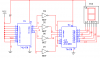
i made a circuit that i have attatched to this post using Multisim7. it uses a numeric keypad ( that i havent made here ), a 74147 that will encode the decimals on the keypad to BCD, a 7447 that will decode the BCD to a 7 segment and a common anode 7 seg display. when i ground a pin on the input of the 74147 (provided other pins are high) the 7 seg display should show the corresponding number. but i dont understand what is the matter with this circuit. when i simulate it, it doesnt work. can someone plz help me out??????????????