Continue to Site

Welcome to our site!

Electro Tech is an online community (with over 170,000 members) who enjoy talking about and building electronic circuits, projects and gadgets. To participate you need to register. Registration is free. Click here to register now.

  • Welcome to our site! Electro Tech is an online community (with over 170,000 members) who enjoy talking about and building electronic circuits, projects and gadgets. To participate you need to register. Registration is free. Click here to register now.

Help with creating a power supply

Status
Not open for further replies.
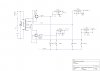
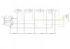
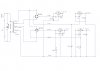
I use to work for a contract electronics manufacturer. They threw out a lot of a customers materials and I was able to get a hold of some of it. Among the items was a power supply board with 2 rectifiers and 4 voltage regulators. I have been working on a power supply board of my own patterned from this board. The customers board used 1 - 7805, 2 - 7812 and 1 - 7912 to obtain the respective voltages. I want to use 1 - 7805, 1 - 7905, 1 - 7812 and 1 - 7912 to get +5, -5 , +12 and -12 respectively. Their circuit and my circuit is attached. My problem is that I don't know how to GROUND the respective regulators to assure the proper voltage(s) output. Can I get help for this OR is this the wrong place?

Thank you
 

Attachments

  • My power supply schematic.jpg
    My power supply schematic.jpg
    140.2 KB · Views: 107
  • Customers circuit board.jpg
    Customers circuit board.jpg
    118.7 KB · Views: 120
1557192731800.png

I move one of the 2200uF caps. You had it going from ground to ground.
The ground pin of each regulator needs to connect ground.
 
BLESS YOU FOR YOUR HELP!!!!!!
I was attempting to follow a previously made circuit board. Looking at this thing, I have no clue how it works!
It's how I was able to do my schematic (but the transformer leads are different)
THANK YOU AGAIN!!!!!

YOU ARE GREAT!!!!!!!!!!!!!!!!!!!!!!!!!!!!!!!!!!!!!!!!!!!!!!!!!!!!!!!!!!!
 
The centertap of the transformer goes to ground.

But, I don't see that you've said what your transformer is.
For the regulators that you're using, you want one secondary to be ~16VAC (8-0-8) for the =/-5 volts. And ~30VAC (15-0-15) for the =/-12 volts.
You use both windings, and both center taps go to ground.

There is some room for variation on the secondary voltage depending on current rating vs. loading and other factors.
 
Last edited:
Below is an interesting circuit that gives two different voltages from a center-tapped transformer with just one bridge rectifier, which might be useful for you, depending upon the transformer output voltages.
Basically the bridge acts as a full-wave bridge for the high voltage output, and a full-wave, 2-diode rectifier for the low voltage output.
Reversing the diodes will give two negative outputs.

upload_2016-8-1_12-8-24-png.100666
 
Ok. I told you that I'm patterning my supply from that old customers board. I did not know it was so messed up. It's funny because I actually have 2 of those boards and I am using one of them in another application. It works just fine. The same thing applies to the transformers. The one that was modified for use on that board has a white molex plug on 5 of the 6 secondaries. They cut-off one of the green ones. As I understand things, the voltage regulators only need +2 volts above the regulated voltage (ie: 7805 > +5 volts PLUS 2 volts = 7 volts). This is what one set of secondaries is (7-0-7). The other is (20-0-20). Now the lower voltage secondaries supply 3 amps of current and the other less than 1 amp. I want at least 1 amp on all of my outputs. Thus I used the two outside secondaries to get 14 volts for the 7812 and 7912, and the center tap and one outside secondary lead to get 7 volts for the 7805 and 7905. Now I understand why they grounded the center tap on the set of secondaries I am not using. Is there anything wrong with doing this? Can I just ground the same center tap they did? Please advise.
 
Can I just ground the same center tap they did? Please advise.
Yes.
Connect one bridge to the 7,7 outputs, and the other bridge to the 20,20 outputs.
Grounding the center-taps for both will then give you a plus and minus output from both bridges.
 
Last edited:
I would not get at least 1 amp from the 12 volt side. Why cant't I use the same single 3 lead secondary? I get 7 volts from the middle lead and outside lead, and 14 volts from the two outside lead. It supplies at least 3 amps.
 
I would not get at least 1 amp from the 12 volt side. Why cant't I use the same single 3 lead secondary? I get 7 volts from the middle lead and outside lead, and 14 volts from the two outside lead. It supplies at least 3 amps.
No. The 7-0-7 winding will make what you need for the ±5V, but not what you need for the ±12 V.

To make your regulators work you need:
● at least +7V from ground into the LM7805
● at least -7V from ground into the LM7905
● at least +14V from ground into the LM7812
● at least -14V from ground into the LM7912
All of your measurements need to be made from ground, not differentially.

If you can't get the current you want from the 20-0-20 secondary, then I'm afraid that the transformer that you have may not be what you need to match your wants. Also, after going through rectification, filtering and regulation, the DC current will be significantly less than the AC secondary rating of the transformer.

PS. Connecting only to the center tap of a winding does nothing, since no current can flow. It's like connecting to one terminal of a battery.
 
Last edited:
A Chris noted, you can't get there from here.
The best you can do is to connect the transformer the way I noted in post #9.
If that's not sufficient current for the ±12 V , then you need another transformer.

And as noted, you need to derate the transformer at least 60% for the DC output current you can draw, as compared to the transformer RMS current rating.
 
Status
Not open for further replies.

Latest threads

New Articles From Microcontroller Tips

Back
Top