TheGingerOne
New Member
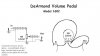
Hello all. I am pretty new to all of this, so I am staring out with what seems liek a very basic project. A devise which will take an input from a guitar (1/4 inch input), and be able to control the volume level with a potentiometer and output the signal to an amp (also 1/4 inch). I am following this very basic diagram whcih I found online.
**broken link removed**
I am running into some problems, and it is kind of frustrating because it looks so simple. Maybe some of you can help me. The diagram does not specify which ends of the input/output are positive/ negative. Does this matter? Also, should the circuit be grounded anyplace? Also, could it not be working because I bought the wrong stuff from RadioShack? Any help is appreciated. Thanks.
Last edited: