Continue to Site

Welcome to our site!

Electro Tech is an online community (with over 170,000 members) who enjoy talking about and building electronic circuits, projects and gadgets. To participate you need to register. Registration is free. Click here to register now.

  • Welcome to our site! Electro Tech is an online community (with over 170,000 members) who enjoy talking about and building electronic circuits, projects and gadgets. To participate you need to register. Registration is free. Click here to register now.

Help with 555 timer? Not very interesting but necessary ;)

Status
Not open for further replies.

Inamabilis

New Member
Hey everyone,
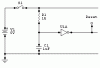
I need to run a 555 monostable (or NAND Gate monostable) timer for about 1 second as soon as power is put to my circuit. The on/off swith for the entire circuit will be a normal SPST switch. I cannot wire the input of the 555 stright to low as then the output of the 555 will never go off! Any ideas anyone?
Oh yeah... the purpose of the 555 would be to reset a number of counters (4510) that my circuit uses, maybe theres a better way of doing this so i dont have to mess arround with trying to get a 555 to activate as soon as the main switch is closed?

Any help would be much appreciated

Thanks

Inamabilis
 
If you just need a startup reset, how about a circuit like the attached. As shown, the Reset goes from high to low after some amount of time. If you reverse the C and the R, you get the opposite result. You can play with the R and C values to get a suitable time delay.

You should also put another R in parallel with the C to discharge the cap when the power is off. It should be an order or two greater than R1.

j.
 

Attachments

  • Reset.gif
    Reset.gif
    2 KB · Views: 925
555 timer

Just moved I haven't unpacked my data books, but as I recall the 4510 requires a positive trigger for reset. Connect a 0.1uf capacitor between the reset pin and the + supply rail. Connect a 100k resistor between reset pin and ground. If you have more than one 4510 to reset, tie all the reset pins together.

Set the 555 up as a one-shot. Connect a 0.1 or larger capacitor from pin 2 to ground. Connect a 10K resistor from pin 2 to + supply rail. When power is applied the 555 will generate a positive going trigger on pin 3. Connect this to the reset pins of the 4510's.
 
Here is a circuit I posted for ymmy in the Chat forum.

It provides a delay of about 3 second. If you leave the relay and driver off, the output of the IC will provide a High pulse for that period. If you need a low pulse, either swap the capacitor and resistor or use another inverter.

Len
 

Attachments

  • Ymmy_s_circuit.gif
    Ymmy_s_circuit.gif
    3.2 KB · Views: 841
ljcox said:
Here is a circuit I posted for ymmy in the Chat forum.

It provides a delay of about 3 second. If you leave the relay and driver off, the output of the IC will provide a High pulse for that period. If you need a low pulse, either swap the capacitor and resistor or use another inverter.

Len
ljcox, can’t thanks enough!!! Seem like this one exactly what I looking for. Will try to build tomorrow and see how it works.
Thank you once again!!!
 
I’m very impressed! Works better then expected, no need to wait long time to discharge huge cap like in transistor version and this circuit ready to be used again within 1sec or even less after On/Off power cycle. I’ve ripped surface mount 74hc14 from my old cd-rom drive so the whole circuit done on the top of chip and circuit dimensions extremely small if compare to transistor version due to huge and ugly 220uf electrolytic capacitor.
As always Thank You for '5 star' help!
 
Status
Not open for further replies.

Latest threads

New Articles From Microcontroller Tips

Back
Top