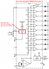
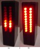
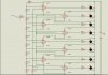
4 393's get you only 8 indicators, ok but pretty coarse. With nothing but 5K (?) and 10K resistors, you cannot build a VU meter because those are not the correct resistor values to create a group of logarithmic-spaced comparator circuits.
Is this homework, classwork, etc?
ak