StudentSA
Member
I am building a project to read a vehicle engine RPM. I have been having sleepless nights trying to design the input signal filtering circuit.
The input signal is taken off the vehicle`s coil negative terminal and ideally should provide a pulse of 12V, 0V, 12V, 0V etc... as the engine cylinders fire.
This is not the case as the signal can have some serious resonance and voltage spikes.
Anyhow, I have found a circuit in a magazine that also uses the signal to do REV Limiting and would like to know if someone could help me understand the input filtering part of it?
I understand a fair fit of electronics so just maybe point out to me the building blocks.
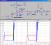
Here is the circuit :

The blocks is just my assumed understanding, Please can you correct my understanding and elaborate on the rest of the circuit.
The Output Vout is used to pulse a input pin of a counter.
The Input Vin is from the coil -ve and has resonance and voltage spikes
Your help is appreciated
The input signal is taken off the vehicle`s coil negative terminal and ideally should provide a pulse of 12V, 0V, 12V, 0V etc... as the engine cylinders fire.
This is not the case as the signal can have some serious resonance and voltage spikes.
Anyhow, I have found a circuit in a magazine that also uses the signal to do REV Limiting and would like to know if someone could help me understand the input filtering part of it?
I understand a fair fit of electronics so just maybe point out to me the building blocks.
Here is the circuit :
The blocks is just my assumed understanding, Please can you correct my understanding and elaborate on the rest of the circuit.
The Output Vout is used to pulse a input pin of a counter.
The Input Vin is from the coil -ve and has resonance and voltage spikes
Your help is appreciated
")

