Continue to Site

Welcome to our site!

Electro Tech is an online community (with over 170,000 members) who enjoy talking about and building electronic circuits, projects and gadgets. To participate you need to register. Registration is free. Click here to register now.

  • Welcome to our site! Electro Tech is an online community (with over 170,000 members) who enjoy talking about and building electronic circuits, projects and gadgets. To participate you need to register. Registration is free. Click here to register now.

help understand sstc

Status
Not open for further replies.

lokeycmos

New Member
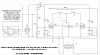
i came across this driverless solid state tesla coil schematic. im finishing up my first sparkgap tesla coil and i am new to solidstate coils. i just need some input on how this works. i asked the author about it and he sent me this:

Interrupter is a circuit that shuts down the coil and turn on times per sec. BPS is Break Per Second, its the interruption rate.

CW is Continuous Wave Mode, its when you run without a interrupter.

The interrupter can be a normal 555 oscillator, the TC4429 also, is only to step-up the voltage for 12V (if your interrupter output is less than that, like me that is 5V) if you make a normal 555 oscillator running by 12V, you can hook the 555 direct at mosfet gate :D


im a little confused about what 'interputer' means. does BPS just mean the falling and rising edges of a wave? will this work without a interupter in CW? what is the difference in performance? my understanding is the IC bumps up the 5v from a square wave source to 12v to run the gates. or if i use a 555 at 12 v i can skip the IC. i just need a little clarification to get a clearer understanding.
 

Attachments

  • Driverless SSTC.png
    Driverless SSTC.png
    364.4 KB · Views: 2,605
I guess if we want to call it an interrupter it would actually be Q3. The job of Q3 is to enable or disable the operation of Q1 and Q2 which drive the coil. So Q3 becomes basically an On/Off switch for Q1 & Q2. The problem is that Q3 won't be turned on and off (like a switch) with a gate signal of only 5 volts (TTL Level). Therefore the designer used the TC4429 6A High-Speed MOSFET Driver. Yes, this gates the MOSFET Q3 with 12 volts. The TC4429 has a TTL compatible input so can be driven with 5 volts. The output is also inverted as 5 volts in is 0 volts out and 0 volts in is supply voltage out. The BPS (Breaks Per Second) would just be the frequency.

I have no clue if the actual circuit would work as drawn but the above is pretty much my take on the interrupter and Q3. We have no shortage of Tesla Coil people here so with luck one will come along. DerStorm comes to mind as he can sniff out Tesla Coils at great distances. :)

Ron
 
Hahaha, thanks Ron for the shoutout :D

Unfortunately I haven't done much with SSTCs either. I have really only made SGTCs in the past. From what I gather, however, this is not actually a Tesla coil. Don't quote me on this, but at first glance, this only seems like an over-complicated version of coil driver. I posted the basic design below.

**broken link removed**

(You'll notice in the link that they call it a "Single transistor solid state Tesla coil", which of course is ridiculous)

This is actually the type of thing that really grinds my gears. Some people create a coil driver (whether it be ignition coil, flyback, etc) and automatically say "Oh hey, I must have made a Tesla coil because it sparks!" I'm sure you know by now, Lokey, that this couldn't be further from the truth. Tesla's actual coils operate through resonance, whereas ignition coils and flybacks operate by forming and collapsing an electromagnetic field. The one you show above does not seem much different. Granted, it does not have a ferromagnetic core, so it is not quite the same as a flyback or ignition coil, but overall I think it runs the same way. I'm sure there are members here more qualified to talk to you about the circuit itself, and whether it really is a Tesla coil or not. But to me, at first glance, I am inclined to say no, it's not.

Do you have a link to the website on which it is featured? I'd be interested to take a look at it.

Regards,
Der Strom
 
Last edited:
so is interupter just a fancy way of saying on-off-on-off... like a squarewave?

Yeah, I guess based on the terminology it interrupts the normal On of the circuit. As I mentioned the actual switching of the circuit on / off is really done by Q3. For what it is worth a Logic Level MOSFET likely have been used for Q3 eliminating the whole 5 volt to 12 volt issue.

Ron
 
Wait, I don't get it.... That's your channel. Where'd the original design come from?

thats not my channel. thats where i got the schematic in his video description. my channel is here:

https://www.youtube.com/user/lokeycmos?feature=mhee

so let me see if i understand this correctly, a standard ttl level squarewave signal goes into pins 2 and 3 of the IC, this converts to 12v to drive Q3. then q3 causes switching on the mosfets. since the mosfets are at opposite ends of the transformer, when one in on the other is off and vice versa. as the mosfets switch, it allows the 55v to flow through L1 and L2 inducing a voltage in the secondary. it looks like the bottom of the secondary also goes through the transformer, is this some type of feedback? im getting a good understanding with ur help!

I was assuming that was some sort of feedback, yes, but I can't say for sure. It doesn't seem like a very safe way to do it, though. In all honesty, that circuit makes very little sense to me :p
 
Yes, if you mean U1 the TC4429. That uses 5 volts, so yes.

Ron
 
I would say that the interrupter is a way of modulating the "Tesla Coil". If you ever did manage to get Q1 and Q2 oscillating at the resonant frequency of the Tesla secondary, then you could use Q3 to modulate that, to play tones or music with the TC.

But I don't see a good way to adjust the switching frequency to match the coil characteristics. At least not easily. And without doing that, then it isn't a Tesla Coil.

JimW
 
Status
Not open for further replies.

Latest threads

New Articles From Microcontroller Tips

Back
Top