Continue to Site

Welcome to our site!

Electro Tech is an online community (with over 170,000 members) who enjoy talking about and building electronic circuits, projects and gadgets. To participate you need to register. Registration is free. Click here to register now.

  • Welcome to our site! Electro Tech is an online community (with over 170,000 members) who enjoy talking about and building electronic circuits, projects and gadgets. To participate you need to register. Registration is free. Click here to register now.
Status
Not open for further replies.

SantiPT

New Member
Hi everyone, i was wondering to make a proyect like this one: Smart Plug Proyect
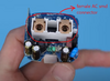
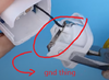
Just for electronics learning purposes. However, i am having problems in finding the differents parts of the female connector (the gnd metalic thing, and the european smd AC connector).

Do anyone know the exact reference of this pieces or closest one? I have been searching in mouser and digikey, but i didn´t be able to find anything similar.

If something isn´t explained cleary pls let me know what is confusing ...
Thanks for the help guys, hope someone can help me :D
 

Attachments

  • femaleConector.png
    femaleConector.png
    336.3 KB · Views: 267
  • gnd thing.png
    gnd thing.png
    152.3 KB · Views: 259
That make sense... that maybe the reason why I’m not finding the comoponents.

I suspect those are all custom parts by the manufacturer of the overall device.

These are the only "DIY" style plug/socket enclosures I am aware of:
I found before this okw web enclosusers but I was looking for doing all by my self, even the case, for complicating more my life :D.
Thanks for you fast response guys!
So my next question is... if I would like to make this kind of personal conector where should I send it for fabrication? There is like a drawing or something like that for this kind of connectors where I can guide throw them? I mean, something like standard measures. Do you know a connector that could fit the solution? Too much questions!!
Thanks guys for helping! :)
 
For the US, I know of this https://www.polycase.com/plug-in-wall-plug-enclosures manufacturer.

I don't know if you would need CE approvals.

Mass production I'm sure is different, but there are companies that stamp stuff, etch stuff or laser print I kew a guy that made model train stuff and he had parts fabricated. The metal could possibly be laser cut and the plastic 3D printed.

The SMT portion is likely selectively plated for solderability.

These guys www.pololu.com do laser, plasma and waterjet cutting.

Somewhere I found the dimensions for the blades for US connectors. I wanted to know because some aliexpress lithium charger stuff I bought seemed to be too loose and they were out of spec.

There are things like foldable blades that would have to be custom.

All I know is, I discovered a really bad problem in the building where I worked with "standard US outlets". We had 430 of them, all out of warranty, but could potentially kill a computer. The ground receptacle contact to the ground connection was frictional and two dissimilar metals. You could see the arc lines when you took an outlet apart.

What could happen due to manufacturing tolerances is that the friction contact didn't mate. If you had a switchng power supply plugged into one of the duplex receptacles and the real ground let go, The other ground to another piece of equipment was at 60 VAC, not 120VAC. if you had RS232 or a parallel port printer that liked to use ground, well the equipment could be toast.

Good luck.
 
What could happen due to manufacturing tolerances is that the friction contact didn't mate. If you had a switchng power supply plugged into one of the duplex receptacles and the real ground let go, The other ground to another piece of equipment was at 60 VAC, not 120VAC.
Can you elaborate on how (or why) that happens? How could it affect the ground on another piece of equipment? (BTW, I don't know what a duplex receptacle is).

Thanks,

Mike.
 
duplex = 2. Duples outlet in the US.

1625021547636.png


There was a piece of stamped brass connecting the circular holes internally.

Mounting would be a U shaped metal around the back of the outlet. Internally, the brass piece and the U shaped piece was just friction. The outlet had screws that put it together,
One of the grounds would come undone based two cord plugged in wiggling the other one.

The two screws on the left goes to the smaller height square contact and they can be separated so one goes to the top one and one goes to the bottom. This is hot. Usually brass.

the one on the right is our neutral. Usually chrome. Same idea.

The one at -45 degrees on the right is ground and usually green. The metal box, if used, is not supposed to be grounded by the mounting screw, but the metal box, if used, needs to be grounded.

Take an RFI line filter such as this one. e.g. corcom

1625017569069.png


usually used in switching power supplies. leakage current is 0.5mA max.
The caps on the load side makes a nice little voltage divider with some of the leakage current.
take the ground away on the right and you have a 1/2 the line voltage voltage source.

So, that stray "ground" has just raised the ground potential of a computer chassis by 60 V if the bond to real earth goes away.

Now lets suppose you have a parallel printer and it;s plugged into a real outlet with a real zero volt ground.

So, our printer sees 63vac+3.5VDC and it isn't happy.

I hope you followed. it happened about 3 or 4 times to me at work.

The first place it happened was an outlet strip.

here

1625019535639.png

is an outlet strip/surge suppressor. That's 3 duplex receptacles and it's what the USA has in our walls. We usually have a duplex receptacle about every 3 meters or so or maybe one on each wall in a bedroom.

If the ground lets go at 12 and 21, and either outlet has a switching power supply and something is plugged into 11, 21, 31 or 32 you have a problem.

I had a mechanical problem with 12's ground and 22's ground.

The 11 positon is top left.

I have an open living room/dinimg room, so the living room is open to a hallway on one side and the dining room on the other. Typically you have one duplex receptacle on each wall. in a bedroom. The living room gets a switched receptacle for a floor lamp. The dining room may have a chandelier. A bedroom has a ceiling light, but I;ve seen some bedrooms eles ewhere that have had switched outlets.
 
For the US, I know of this https://www.polycase.com/plug-in-wall-plug-enclosures manufacturer.

I don't know if you would need CE approvals.

Mass production I'm sure is different, but there are companies that stamp stuff, etch stuff or laser print I kew a guy that made model train stuff and he had parts fabricated. The metal could possibly be laser cut and the plastic 3D printed.

The SMT portion is likely selectively plated for solderability.

These guys www.pololu.com do laser, plasma and waterjet cutting.

Somewhere I found the dimensions for the blades for US connectors. I wanted to know because some aliexpress lithium charger stuff I bought seemed to be too loose and they were out of spec.

There are things like foldable blades that would have to be custom.

All I know is, I discovered a really bad problem in the building where I worked with "standard US outlets". We had 430 of them, all out of warranty, but could potentially kill a computer. The ground receptacle contact to the ground connection was frictional and two dissimilar metals. You could see the arc lines when you took an outlet apart.

What could happen due to manufacturing tolerances is that the friction contact didn't mate. If you had a switchng power supply plugged into one of the duplex receptacles and the real ground let go, The other ground to another piece of equipment was at 60 VAC, not 120VAC. if you had RS232 or a parallel port printer that liked to use ground, well the equipment could be toast.

Good luck.

Thanks for your response, maybe could be interesting sending the pieces to see if they can fabricate, I have to do my own and custom component I guess. Pretty good idea send to them for cnc milling. I’ll do when I do have some time. If you guys are interested I could post how goes the 3D design of the “custom” component, also if someone more have any new ideas it will be welcome :D
 
Status
Not open for further replies.

Latest threads

Back
Top