Continue to Site

Welcome to our site!

Electro Tech is an online community (with over 170,000 members) who enjoy talking about and building electronic circuits, projects and gadgets. To participate you need to register. Registration is free. Click here to register now.

  • Welcome to our site! Electro Tech is an online community (with over 170,000 members) who enjoy talking about and building electronic circuits, projects and gadgets. To participate you need to register. Registration is free. Click here to register now.

Help reviewing this Circuit.

Status
Not open for further replies.

Gotrek

New Member
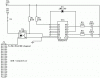
Can someone look at the following circuit and let me know if it should work, basicly it's a mod for my Xbox, I'll have two LEd rings one green one red, the mod should make it be lit up green at all times but flash red when there is disk activity. I didn't come up with the design just made a diagram of it in Circuit Maker Pro 2000 :) 
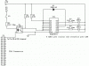
I just want to make sure it will work before I build it. Ask me any questions and I'll answer the best I can.
I was wondering if On output pins o0, o2, 03, 05, 07 should be connected to the 12V source or even bridged to each other like on the input side

Please copy and paste the following in your browsers adress line to view it

http://www.geocities.com/ddduval/XBOX.gif

Or see attachment below
 

Attachments

  • XBOX.gif
    XBOX.gif
    5.4 KB · Views: 877
You actually don't require ULN2803 driver. But if you want to use it then you should remove those two 10k pull up resistor terminals from +12V supply and connect it to +5V supply. 5V pullup is required at the input side and not 12V.
What is 1N4148 diode used for?

Alternative:
1) Directly connect a LED to 5V through 330 ohm resistor and ground its cathode.
2) Similar connection for IDE but instead of grounding the cathode, connect it to pin 39 of IDE. i.e the same way you have connectd the opto-coupler LED but through a 330 Ohm resistor.
 
kinjalgp said:
You actually don't require ULN2803 driver. But if you want to use it then you should remove those two 10k pull up resistor terminals from +12V supply and connect it to +5V supply. 5V pullup is required at the input side and not 12V.
What is 1N4148 diode used for?

Alternative:
1) Directly connect a LED to 5V through 330 ohm resistor and ground its cathode.
2) Similar connection for IDE but instead of grounding the cathode, connect it to pin 39 of IDE. i.e the same way you have connectd the opto-coupler LED but through a 330 ohm resistor.

To be perfectly honest I don't know what the Diode does, I guessed it was there to keep the system safe? I know thats why the optoisolator is there, to prevent from frying the mainboard in case something happens.

Here is the original diagram

**broken link removed**

And Article
**broken link removed**

Sorry I can't help more, I can't design them I can just solder them together :)
 
Thanks for the advice guys keep the advice coming I'll check back tomorrow morning I'm off now. Any reason why the circuit won't work the way it is now? Even with the extra parts?

Remember keep it simple talk to me like I'm three :)
 
Looks to me like the blue LED will be on and red LED will be off when HDD input is high, and vice-versa when HDD input is low. With this circuit, the diode is required, but there are simpler ways of accomplishing the same thing.
I agree with Sebi that you need a current-limiting resistor in series with the optocoupler input, unless it's built in to the HDD output pin. And it's OK to leave the 10k resistors connected to +12v if you want. ULN2803 is designed to switch with 5 volt logic inputs, but 10k resistor pullups to 12v won't hurt them.
 
What Ohmage (If thats a word) does the resistor need to be, I mean the one between the switch and Octocoupler?
 
You can calculate it using this equation:
R = (Vs-Vf)/If

Vs = Supply Voltage = 5V
Vf = Forward Voltage of Opto-LED i.e around 2V
If = forward current of LED i.e around 10-15mA

Usually series resistor value @ 5V varies between 120 Ohms to 330 Ohms depending on type of LED. Use 220 Ohm for your circuit. It will work without any problems.
 
You need to sink a bit more than 1mA through the collector on the diode and Vce is about 12V, so if you set the forward current through the led to between 2-20mA you will be fine. The forward voltage of the led is about 1.25V. for 10mA, you need a 375ohm resistor. The closest standard values are 360 or 390 -- either would work.
 
You're tlaking about the resistor I will place on each LED in the ring correct? Yes I will calculate the proper resistor value in that portion of the circuit when I choose the LED's I'm goiung to se since the specs vary slightly, I just put 500 ohm to put something :)
The resistors will probably be 100 ohm, the diodes are 2.2v forward and rated for 30ma and will be getting 12v - If I had only one I think that would require a 330 ohm resistor correct?
There will also be more then one LED in the ring probably 6 of each colour all in parralel each with a resistor.
 
Updated diagram

Just to make sure I understand right, we have this now correct (added 220ohm resistor and added note for LED resistors (LED's in a ring in connected paralel))
 

Attachments

  • XBOX_158.gif
    XBOX_158.gif
    5.8 KB · Views: 792
I was speaking of the dropping resistor in series with the LED in the 4N25. Kinjalp and I posted at almost the same time. You can use the 220 for 17mA, it does not make much difference -- either value will give you close to the maximum output in the photodiode.

As for the other LEDs, you can use a 330 ohm if you use one LED, if you have two in parallel, then 180 or 150 would work.
 
crust said:
I was speaking of the dropping resistor in series with the LED in the 4N25. Kinjalp and I posted at almost the same time. You can use the 220 for 17mA, it does not make much difference -- either value will give you close to the maximum output in the photodiode.

As for the other LEDs, you can use a 330 ohm if you use one LED, if you have two in parallel, then 180 or 150 would work.

Ah ok sorry I really appreciate the help guys,

I'll look through my parts stash to see if I have either a 220ohm or 360-390 ohm resistor since I bought all my parts already. I've got about 1 bazillion resistors so I'll pull out my trusty meter and find one. Thanks again. Basicly the goal is to have 2ma through the input at the Vce on the Optoisolator? So any resistor from 220 ohm - 2.2k ohm (although 220 to 390 will b better for me to find anyways.
 
Yes it will work on PC HDD also.
But on most computers, these two LEDs are already present and there is a separate connector for them on the motherboard. So if you want more colored LEDs, use buffer and connect as many as you want.
 
Status
Not open for further replies.

Latest threads

New Articles From Microcontroller Tips

Back
Top