Continue to Site

Welcome to our site!

Electro Tech is an online community (with over 170,000 members) who enjoy talking about and building electronic circuits, projects and gadgets. To participate you need to register. Registration is free. Click here to register now.

  • Welcome to our site! Electro Tech is an online community (with over 170,000 members) who enjoy talking about and building electronic circuits, projects and gadgets. To participate you need to register. Registration is free. Click here to register now.

Help repairing Distortion on Denon PMA-350se Amplifier

Status
Not open for further replies.

sfoxon

New Member
Hello Hive Mind!

I have the Denon PMA-350se power Amplifier, which has some distortion on the LH channel only. I have been playing with Sine waves and probing with the Oscillsope, but am limited in what I can do. A service manual with circuit diagrams can be found: edit: Thank you for pointing out no link: https://www.vintageshifi.com/repertoire-pdf/pdf/telecharge.php?pdf=Denon-PMA-350-Service-Manual.pdf

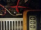
I last pick up a clean sine wave before the Volume pot. Between the volume pot and the Big Transistors on the heat sink, I cannot pick up a signal, as probing changes the sound and the readout is very dirty. At input to the big transistors, the sine wave is showing distortion. So somewhere between volume and bridge rectifier essentially.

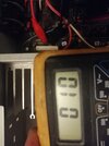
The good news is I can share the distortion with you:
IMG_20211217_200515.jpg


This looks like rectifier crossover distortion! and YET I have replaced: The main transistors (TR361-4), main smoothing caps (C003-4), DC blocking caps (C327-8), more caps C013-4 and C324-5 and also the OpAmp Chip. All to no avail.

What next?
 
Last edited:
It looks like a bias fault at the output stage.

Does it have a bias adjustment pot? If it does, it try wiggling that either way a fraction, as it may just be dirty and the wiper has lost contact.

Edit - found a schematic.
It does have bias adjustment pots; VR351 is the one for the left channel.

Before changing anything, measure the voltage across pins 1&3 of "TPR", the right channel bias test point. That will presumably be in a reasonable range.

Then set the left hand bias to give the same voltage across pins 1&3 of "TPL".

I found the service manual here, for info:
 
Last edited:
Thank you for your reply - really useful! I think that spraying with deoxit did help a little, so maybe I am battling multiple issues!
I'm very new to working with circuits that involve silicon so thank you for beign so clear and helpful!

Would this likely point to a capacitor issue, or a transistor issues? From what I can tell, the two channels pull power from the same power rails, so likely not in the power circutry?

Thank you so much for your input, I am most grateful!

No, it's not likely to be in the power supply, and there's no such thing as 'rectifier crossover distortion' - crossover distortion is caused by too little bias in the output stage at low volume, and your scope picture (at low power) is a classic example of that.

As suggested above, check the bias settings on TPR and TPL.

There's VERY little that can cause crossover distortion, and (as also suggested above) by FAR the most likely issue is simply a dirty bias preset. However, the (poorly designed) bias setting appears to revert to maximum bias if the pot slider becomes open circuit, which should prevent cross over distortion, but could kill the amp.

But again, check the voltages on TPR and TPL, but do it very carefully, it's VERY, VERY easy to blow a transistor amp by careless application of meter probes.
 
Sorry for the delay in reporting back- the rabbit hole deepens!

Thank you for your reply, you are msot helpful!

I put some test leads across TPR (working channel) test points and readjusted as per the manual to get 10mv. (Its a fine art it seems!)
On the TPL (crossover distortion channel) I only got a reading of 0v across the entire sweep of the variable resistor. I have replaced the varaible resistor to no avail, and I can't see any visible sign of a short anywhere, and the signal is getting through, albeit degraded.
 

Attachments

  • IMG_20220113_203438.jpg
    IMG_20220113_203438.jpg
    4.6 MB · Views: 240
  • IMG_20220113_203312.jpg
    IMG_20220113_203312.jpg
    4.5 MB · Views: 235
That implies a semiconductor failure; it could be just about any transistor in that channel, or the diode feeding the bias control transistor..
 
That implies a semiconductor failure; it could be just about any transistor in that channel, or the diode feeding the bias control transistor..

Seems far more obvious than that, more likely the Vbe multiplier TR355 is S/C, the manual shows the voltages on the collector and emitter, well worth checking those. If they are the close to been the same, then the transistor is probably short.
 
The voltage on the collector and emitter is sitting around +/-0.5v; the other channel is normal 1.05v/-1.18v as per the circuit diagram!

1642278676536.png


I replaced the 2SC1815 pictured, and no change (naturally)

I am awaiting the other 2 pairs of transistors in the 4. Will keep you updated when they have arrived and are fitted...
 
Check if D355 is S/C - the circuit is a Vbe multiplier, essentially a variable zener diode, with the voltages +/-0.5V I wouldn't have tried changing the transistor. The higher the voltage, the higher the current in the output stages, and if it's too high the output devices will be destroyed, likewise the lower the voltage the lower the current, to the extent of getting crossover distortion.

It's common practice when repairing such amplifiers to short out the Vbe multiplier to help ensure the new transistors don't self destruct - then once it's working, with crossover distortion, then remove the short and check/adjust the quiescent current.
 
check the resistance of R369. if it' open, that would cause TR355 to turn full on and shut down your bias.
 
Status
Not open for further replies.

Latest threads

New Articles From Microcontroller Tips

Back
Top