Electro Tech is an online community (with over 170,000 members) who enjoy talking about and building electronic circuits, projects and gadgets. To participate you need to register. Registration is free. Click here to register now.
Welcome to our site! Electro Tech is an online community (with over 170,000 members) who enjoy talking about and building electronic circuits, projects and gadgets. To participate you need to register. Registration is free. Click here to register now.
Page 9 shows pin 9 of the first LM3915 connected to pin 1 of the second LM3915 and the 11th LED. It explains that when the 11th LED lights then pin 9 drops 1.5V or more which turns off the 10th LED.
Your circuit will work wrong if a very important supply bypass capacitor close to the ICs is missing. The supply bypass capacitor C1 is shown on the first schematic in the datasheet.
It didnt worked like with the opamp showed in page 9, i used single polarity opamp is that the problem?
Page 9 does not have an opamp. The opamp is shown in figure 6 on page 12.
When the input signal swings negative then a single-supply opamp might have its input damaged unless it has a dual-polarity supply.
Which opamp did you use?
The circuit in post #41 will not turn off LED #10 when a higher LED lights when in the DOT mode because pin 9 of the first LM3915 is not connected to pin 1 of the second LM3915.
Page 9 shows pin 9 of the first LM3915 connected to pin 1 of the second LM3915 and the 11th LED. It explains that when the 11th LED lights then pin 9 drops 1.5V or more which turns off the 10th LED.
Your circuit will work wrong if a very important supply bypass capacitor close to the ICs is missing. The supply bypass capacitor C1 is shown on the first schematic in the datasheet.
i did the same way as shown i connected the pin 1 of 2nd ic to the pin 9 of 1st ic, i even connected 20k resistor to 11th pin of ic1 to vcc, i used 100uf caps as bypass to both ics.... but still the 1st led of ic2 light very dim and keeps glowing when voltage is higher to it, and it switches of when the voltage is lower to it.i want it to completly shut when the voltage is higher and leds above it are lighting.
Page 9 does not have an opamp. The opamp is shown in figure 6 on page 12.
When the input signal swings negative then a single-supply opamp might have its input damaged unless it has a dual-polarity supply.
Which opamp did you use?
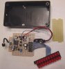
ya you are right , its on figure 6.....i mean dat only. i am using ap358 half, for peak detection and other half for cascading as shown in figure 6.but the second half didnt worked.so what i did is this as shown in View attachment 66969 ,it is working but the leds reach max to 14 th or 15 th led not above
On page 9 the datasheet says that the first LED of the second LM3915 (the 11th LED) might glow faintly when it should not be lighted. It says to connect a 10k resistor parallel to the 11th LED so that it does not light when it shouldn't.
The peak detector circuit prevents a negative voltage into the input of the opamp.
The Circuit in the datasheet has a 10V full-scale input voltage so the power supply to the LM3915 ICs, peak detector opamp and opamp for the LM3915 must be 12V or 13V. Or a lower supply voltage can be used if the full-scale voltage is reduced by reducing the value of the 13k resistor.
so the power supply to the LM3915 ICs, peak detector opamp and opamp for the LM3915 must be 12V or 13V. Or a lower supply voltage can be used if the full-scale voltage is reduced by reducing the value of the 13k resistor.
i am using 12 v supply, and now where should i use 13 k resistor?
What will happen if i wil use full wave precision peak detector rather than half wave like yours?
On page 9 the datasheet says that the first LED of the second LM3915 (the 11th LED) might glow faintly when it should not be lighted. It says to connect a 10k resistor parallel to the 11th LED so that it does not light when it shouldn't.
Breadboards have intermittent contacts. They have too much inductance and capacitance for RF circuits. Their millions of long wires pickup interference.
13k is for reference voltage but on which pins shoud i connect it
hey wts up, i was out of town....i build up dat circuit again on pcb and it worked like a charm,,, now the problem is i want smother transitions, as in dot mode i want only one led to on at an instant of time,, but now there are atleast2-3 on sometimes four...how can i solve this problem
you mean to say average detector insted of peak detector????? can u give circuit,, i saw ur links......they seemed me confused lil bit sorry its my fault but can u help in it? i want the leds to go up and down smoothly, ie only one led should move, not group of two or three
My LM3915 Sound Level Indicator project has a peak detector and in the DOT mode it shows ONE lighted LED bouncing around.
The datasheet says that oscillation or excessive noise causes a few LEDs to light in the DOT mode (from using a breadboard?).
Hint, hint: don't use a breadboard.
I made my project on a stripboard with all strips cut to be fairly short so they do not pickup interference. Its enclosure is plastic, not metal.
My circuit has extra gain and an AGC circuit so that it has a lot of gain when the levels are low then it reduces the gain when the levels are high. It shows a pin dropped on the floor in the next room and also shows very loud sounds.
now the problem is i want smother transitions, as in dot mode i want only one led to on at an instant of time,, but now there are atleast2-3 on sometimes four...how can i solve this problem
Two things I can think of.
1) bread board problems causing oscillations. You may have a opamp or LM3915 oscillating. OR Ground noise. Power power supply noise.
2) the capacitor in the peak detector needs to be larger. That will hold the value longer. Try a much larger cap and see if it helps.
My LM3915 Sound Level Indicator project has a peak detector and in the DOT mode it shows ONE lighted LED bouncing around.
The datasheet says that oscillation or excessive noise causes a few LEDs to light in the DOT mode (from using a breadboard?).
Hint, hint: don't use a breadboard.
I made my project on a stripboard with all strips cut to be fairly short so they do not pickup interference. Its enclosure is plastic, not metal.
My circuit has extra gain and an AGC circuit so that it has a lot of gain when the levels are low then it reduces the gain when the levels are high. It shows a pin dropped on the floor in the next room and also shows very loud sounds.
thanx alot for this circuit, i am gonna make this circuit tommorow, but before making i wana ask questions-----
please see this circuit the questions are in it~~~~~~>View attachment 67211
Two things I can think of.
1) bread board problems causing oscillations. You may have a opamp or LM3915 oscillating. OR Ground noise. Power power supply noise.
2) the capacitor in the peak detector needs to be larger. That will hold the value longer. Try a much larger cap and see if it helps.
Good grief or bad grief! TOO MANY simple questions. Please LEARN the basics of electronics.
My Sound Level Indicator project is designed to be powered from a little "9V" rechargeable Ni-MH battery or its little 9V charger.
Some of its resistors and the LM3915 IC will burn if a 12V supply is used. Redesign the circuit so a 12V supply can be used.
1) The low dropout 5V regulator allows the preamp and oscillator to have a regulated 5V voltage. With your higher supply you can use an ordinary 7805 5V regulator.
2) R16 shares the heating when the supply is 9V, when there are two red LEDs in series at each output and when the current is set at about 26mA. Recalculate the value of R16 and its amount of heating when your power supply voltage is much higher.
The low dropout regulator needs C6 and C7.
3) The preamp and oscillator are designed for a +5V regulated supply. Redesign the circuit for a different voltage if you want.
4) The mic input is too sensitive for a line level input. An attenuator (made with a few resistors) is needed to reduce the sensitivity so a line level input can be used. Also the resistor R1 that powers an electret mic must be removed.
5) The datasheet for the LM3915 says that the first LED might light dimmly when it is supposed to be off because it is fed a small current so it can be the 11th LED when two or more chips are cascaded. The datasheet says to use a 10k resistor parallel to the SINGLE LED. I used 22k for R18 since my circuitry has TWO red LEDs in series.
6) The datasheet has a graph of output current which is determined by multiplication of the current fron pin 7 to ground. Each output in my circuit has a current of 26mA when switched to Bright and is 5mA when switched to Dim.
7) If you use transistors at the outputs for multiplexing then R16 and C7 might not be needed. C6 is needed when the circuit is powered from a battery or a very cheap DC power supply.
but i wanted to ask more mr COOOOOL
i was tryn to run more leds by using transistor, but m facing a problem...led is not turning completely off.....there is still some current flowing through it when there is no output from 3915
here is the circuit i am usingView attachment 67225
Your circuit does not have a very important current-limiting resistor for the LEDs so they will instantly burn out!
The outputs of the LM3915 are OPEN without a signal so the LEDs should be turned off.
If you use a lousy breadboard then the millions of long connecting wires pickup interference and make everything go crazy.
Please learn about the basics of electronics.
GEEEZ. There should be a separate website for theez nOObs who know NOTHING about electronics!
i was tryn to run more leds by using transistor, but m facing a problem...led is not turning completely off.....there is still some current flowing through it when there is no output from 3915
here is the circuit i am usingView attachment 67225
1) the LM3915 is built to drive LEDs not a transistor. Change R2 from 100k to 10k or maybe 1k to get the transistor to turn off.
2)I do not know what your VCC is. You have VCC across 3 LEDs with no current limit resistor. This is a bad idea. You need a resistor to limit current in the LEDs.
This site uses cookies to help personalise content, tailor your experience and to keep you logged in if you register.
By continuing to use this site, you are consenting to our use of cookies.

 but still the 1st led of ic2 light very dim and keeps glowing when voltage is higher to it, and it switches of when the voltage is lower to it.i want it to completly shut when the voltage is higher and leds above it are lighting.