Hi,
Up to date, I'm familiarized with simple transistor circuits, and I know how to work with small-signal equivalent circuit, to work out input/output impedance, current/voltage gain, .... but I get intro trouble when trying to fully understand how complex circuit work.
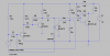
As an exercise, I set myself the goal with this circuit (a small amplifier for faint sounds). If any of you think it is definitely not a good example to learn from, please tell me. What I really want is to learn how to face the analysis of this kind of circuits.
I attached a LtSpice schematic I just done to aid me (but simulation doesn't really match with the circuit explanation given by its author). I got the idea from this web page:
Amplified Ear - RED - Page38
As far as I know, when there're several stages, you should work output impedance from right to left, and input impedance and gain from left to right. First you get the bias, or DC op point (this is not a problem for me) and then work out the AC equivalent circuit, and replace all transistors with a equivalent (I like and always use an hybrid-pi model, **broken link removed**).
But after hours, I just get stuck with this circuit.
The first thing I don't know how to handle is that negative feedback from Q3 to the input. I do understand, from a qualitative point of view, that it turns Q1 down when the signal goes up (negative feedback), but I don't see the full image clear.
Also, When biasing a common-emitter with a base-collector feedback resistor (like Q2 and Q4), I don't know how to work out the impedances (in the hybrid-pi model, that resistor appears between base and collector, that is, from input to output, and it confuses me).
Sure I'm not focusing the problem the right way, and that is what I would like to.
Any advice/help is appreciated.
I'm not looking for the solution, but for learning how to do myself, and I promise to work hard on it")
Thank you!
Up to date, I'm familiarized with simple transistor circuits, and I know how to work with small-signal equivalent circuit, to work out input/output impedance, current/voltage gain, .... but I get intro trouble when trying to fully understand how complex circuit work.
As an exercise, I set myself the goal with this circuit (a small amplifier for faint sounds). If any of you think it is definitely not a good example to learn from, please tell me. What I really want is to learn how to face the analysis of this kind of circuits.
I attached a LtSpice schematic I just done to aid me (but simulation doesn't really match with the circuit explanation given by its author). I got the idea from this web page:
Amplified Ear - RED - Page38
As far as I know, when there're several stages, you should work output impedance from right to left, and input impedance and gain from left to right. First you get the bias, or DC op point (this is not a problem for me) and then work out the AC equivalent circuit, and replace all transistors with a equivalent (I like and always use an hybrid-pi model, **broken link removed**).
But after hours, I just get stuck with this circuit.
The first thing I don't know how to handle is that negative feedback from Q3 to the input. I do understand, from a qualitative point of view, that it turns Q1 down when the signal goes up (negative feedback), but I don't see the full image clear.
Also, When biasing a common-emitter with a base-collector feedback resistor (like Q2 and Q4), I don't know how to work out the impedances (in the hybrid-pi model, that resistor appears between base and collector, that is, from input to output, and it confuses me).
Sure I'm not focusing the problem the right way, and that is what I would like to.
Any advice/help is appreciated.
I'm not looking for the solution, but for learning how to do myself, and I promise to work hard on it
Thank you!