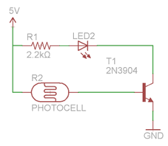
I'm a newbie....") and could really use some help. I have a project that will be powered by (3) 18650 li-ion batteries in series. I will have an ON/OFF rocker switch that a user will turn to the ON position during daylight hours. Then, at dusk/dark, the power will flow thru the circuit triggered by a photoresistor. I simply want power to be ON or OFF based on the photoresistor's resistance..... very basic, right? I currently have a 'photocell module' from a basic outdoor light sensor. It has a relay, transistors, mosfets, capacitors, resistors all over the small PCB. Can I handle my ON/OFF needs in a simpler way? I am currently waiting on some photoresistors, some 2N3904 transistors and assorted resistors to arrive so I can put something together.... I found a circuit while doing research yesterday that might be what I need to follow, but wanted to confirm with the knowledge base here..... any suggestions or ideas are much appreciated. Thanks -John
and could really use some help. I have a project that will be powered by (3) 18650 li-ion batteries in series. I will have an ON/OFF rocker switch that a user will turn to the ON position during daylight hours. Then, at dusk/dark, the power will flow thru the circuit triggered by a photoresistor. I simply want power to be ON or OFF based on the photoresistor's resistance..... very basic, right? I currently have a 'photocell module' from a basic outdoor light sensor. It has a relay, transistors, mosfets, capacitors, resistors all over the small PCB. Can I handle my ON/OFF needs in a simpler way? I am currently waiting on some photoresistors, some 2N3904 transistors and assorted resistors to arrive so I can put something together.... I found a circuit while doing research yesterday that might be what I need to follow, but wanted to confirm with the knowledge base here..... any suggestions or ideas are much appreciated. Thanks -John
BTW, I understand that the current will flow via the POLR. This particular schematic I found incorporates a small LED and I assume that is why there is a 2.2k Ω resistor in line. Ultimately, in my project, the 12v will power a few different lower voltage items (5v) as well as (2) high power 3w LEDS. I will have a step down and LED driver as needed, downstream.
and could really use some help. I have a project that will be powered by (3) 18650 li-ion batteries in series. I will have an ON/OFF rocker switch that a user will turn to the ON position during daylight hours. Then, at dusk/dark, the power will flow thru the circuit triggered by a photoresistor. I simply want power to be ON or OFF based on the photoresistor's resistance..... very basic, right? I currently have a 'photocell module' from a basic outdoor light sensor. It has a relay, transistors, mosfets, capacitors, resistors all over the small PCB. Can I handle my ON/OFF needs in a simpler way? I am currently waiting on some photoresistors, some 2N3904 transistors and assorted resistors to arrive so I can put something together.... I found a circuit while doing research yesterday that might be what I need to follow, but wanted to confirm with the knowledge base here..... any suggestions or ideas are much appreciated. Thanks -JohnBTW, I understand that the current will flow via the POLR. This particular schematic I found incorporates a small LED and I assume that is why there is a 2.2k Ω resistor in line. Ultimately, in my project, the 12v will power a few different lower voltage items (5v) as well as (2) high power 3w LEDS. I will have a step down and LED driver as needed, downstream.

 . I've got one of these connected to trigger the LED on. I have it connected to a breadboard along with a 2v, 20ma 5mm led. I'm feeding the sensor with 5v and the led with 3.3v with 68 Ω on the + side. I have a 2N3904 transistor on the neg side with the gate triggered by 3.3v from the signal pin on the sensor. My issue is that the led will come on for approx 3 sec, then off for approx 6 sec, then back on and will continue doing this. It seems like there is some voltage bleeding through somewhere and loading a capacitor or something. Any suggestions for troubleshooting? Thanks.