Continue to Site

Welcome to our site!

Electro Tech is an online community (with over 170,000 members) who enjoy talking about and building electronic circuits, projects and gadgets. To participate you need to register. Registration is free. Click here to register now.

  • Welcome to our site! Electro Tech is an online community (with over 170,000 members) who enjoy talking about and building electronic circuits, projects and gadgets. To participate you need to register. Registration is free. Click here to register now.

help needed for LED array..

Status
Not open for further replies.

civvie

New Member
Hello all.

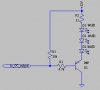
I have modified a LED audio VU meter **broken link removed**to have 10 LEDs shine at once for every 1 LED on the meter. It is 10 LEDs long so there are 100 in total (the kit on the link has 12 leds but I am only using the middle 10). I have made a prototype with 10x red 12v LEDs running in parallel off every point, and it works well but probably could be brighter. At the moment I am only using a 9 volt supply too, I plan on using a 12v one.

It is my aim to have 4 of these meters, Red, Yellow, Green and White. I was initially just going to purchase another 300 12v LEDS and make up the other 3 but now I am thinking that I can use lesser voltage LEDs with a resistor (muc cheaper, especially for white leds). If I can get better results this way I may re-do the red 12 volt ones. Also, is there a benefit to running them in series? They seem to work well in parallel but it has been suggested to me to run them in series.

My question in a nut shell:

What is the best way to wire 10 leds to every one of the leds on **broken link removed**.

any help much appreciated
 
The circuit is designed for only one LED at each output. 10 LEDs require 10 times the current that will probably blow up the driver transistors.

Only LEDs that are matched by the manufacturer can be directly connected in parallel. If they are not matched then the one with the lowest voltage will hog most of the current and burn out. Then the next one with the lowest voltage will burn out, etc. If you keep the LEDs very dim then they will not burn out.

White LEDs use about 3.5V each. If the circuit survives a 12V supply then 3 white LEDs in series might be able to be driven at each output, not 10.
 
Anyone? Have I provided enough information? Cheers.

hi,
I 'think' I follow your description.:)

Are you saying that for each LED on the original design, you want to drive 10 more.?

If you use white leds they have a Vdrop of about 3V to 3.5V, so cannot put many in series on a 12V supply
 
3 in series with a 33 ohm current limiting resistor. if you use a transistor driver off of each output, you could parallel 3 strings for a total of 9 white LED's
green LEDs could be run in series strings of 4, yellow or red in strings of 8 (depending on the yellow led's, some types are 1.4V, some are 2.6V devices and some are 2.0V)
 
That's right. For every LED on the original design I want 10 instead.
I have built a prototype with 12v RED LEDs (10 in paralel off every point) and it works great, but I'm not sure if the LED's are as bright as they could be.

I am just woundering if this can be improved apon with lower voltage LED's or a different array etc.
 
With 10 LEDs in parallel then the available current for a single LED in the original device is now spead amongst 10 LEDs. So each LED is 1/10th as bright as it should be. If you increase the current then some of the LEDs and maybe the transistors will burn out.
 
Thanks for all the replies. This is helping a lot.

With 10 LEDs in parallel then the available current for a single LED in the original device is now spead amongst 10 LEDs. So each LED is 1/10th as bright as it should be. If you increase the current then some of the LEDs and maybe the transistors will burn out.
Today 02:31 PM

OK. So if the circuit is expecting 1x 12v LED. What voltage should each LED be if I have 10 of them connected in parallel?

Only LEDs that are matched by the manufacturer can be directly connected in parallel. If they are not matched then the one with the lowest voltage will hog most of the current and burn out.

Will connecting them in series fix this issue?
Does this change the equation in my first question?


The LEDs do not have to be as bright as the possibly can be. I am just trying to improve apon my current arrangement of 10x 12v LEDs in parallel.
(BTW, this is for a lighting effect to be hooked up to bands drum machine for live shows)
 
OK. So if the circuit is expecting 1x 12v LED. What voltage should each LED be if I have 10 of them connected in parallel?
We don't know the circuit so we don't know how much more current the driver transistors can survive. A complete re-design might be needed for 10 LEDs to be driven brightly from each driver transistor.


Will connecting them in series fix this issue?
Only 2 or 3 white LEDs can be in series when the supply is 12V.

Does this change the equation in my first question?
The total voltage of LEDs in series must be less than the supply voltage. Maybe more since we do not know the circuit.

The LEDs do not have to be as bright as the possibly can be. I am just trying to improve apon my current arrangement of 10x 12v LEDs in parallel.
(BTW, this is for a lighting effect to be hooked up to bands drum machine for live shows)
You might as well do it properly (bright).
 
judging by the picture, it's a circuit that uses a Sanyo chip similar (but a different pinout, and only 6 LEDs per channel) to the LM3914/15. the output pin for the LED is an open collector output. the max current sinking for these outputs is only about 50mA. with the following circuit, you could run the LEDs in series strings and stack the strings in parallel. with a 2N3906 transistor, you could have up to about 5 strings (consisting of the 33 ohm resistor and 3 WLEDs) in parallel. the input to this circuit is the OC output of the VU meter chip. this circuit includes the pullup resistor for the OC output and a current limiter for the base of the transistor.
 

Attachments

  • ocleddrvr.jpg
    ocleddrvr.jpg
    7.7 KB · Views: 161
There are realy no 12 volt leds, the ones you are finding are a standard led that has a limiting resistor built into them. so when you use standard leds they will need current limiting resistors. When you buy more leds they should have their forward voltage and current limit so you can calculate a range for them
 
judging by the picture, it's a circuit that uses a Sanyo chip similar (but a different pinout, and only 6 LEDs per channel) to the LM3914/15

Actually, no, it has not chip at all. It uses a series of transistors which are forward biased in a sequence depending on the input level. I aquired a circuit diagram that I will post later today which should clear up the situation.

Thanks for all the input, I'm learning quickly. (I have not delt with LEDs before)
 
**broken link removed**

OK here is the schematic.

I want 10 LEDs for very single LED from D15 - D24 (There are 12 LEDs in the meter but I will not use the first and last ones)
 
unclejed613:
...with the following circuit, you could run the LEDs in series strings and stack the strings in parallel.....


Could a similar modification work with the circuit I have posted above?


I need to order the LEDs this week, at the moment my best option is to buy LEDs with the lowest voltage available and just string them off each of the points, and suffer the reduction in brightness.
 
parallel 3 strings of white LED's with 33 ohm current limiters. that will give you 9 LEDs of approximately equal brightness. to do 10 would cause 4 LEDs to be dimmer than the rest. this will be about 60mA per transistor, which should be well within the limits of most transistors, such as 2N3904 or 2N2222.
 
Does the circuit give the transistors enough base current for a collector load of 60mA? I doubt it.
 
Your schematic does not have a transistor part number and does not have resistor values. So we cannot calculate how many LEDs each transistor can drive.
 
with a 2N3904, with a minimum beta of 100, 600uA would be required for driving a 60ma load, and i think 2N2222s have about the same beta range.
 
Beta is used when a transistor is a linear amplifier with plenty of collector to emitter voltage. Most transistors use a base current that is 1/10th the collector current when used as a saturated switch.
 
Status
Not open for further replies.

Latest threads

New Articles From Microcontroller Tips

Back
Top