A simple diode-capacitor is not a good way to see AC voltages that are small. It takes 0.6 volts to turn on a diode.
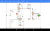
Here is a circuit from the data sheet of the LT1078. It will work with very small AC voltages.
If you build this circuit use a "R-R input & R-R output, low voltage op-amp". Or at least use a op-amp that will work when the input is at ground. See "input common mode voltage range".
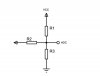
Here is my modification. I added a switch for a gain of 1 or 10.
View attachment 114392
View attachment 114393