Continue to Site

Welcome to our site!

Electro Tech is an online community (with over 170,000 members) who enjoy talking about and building electronic circuits, projects and gadgets. To participate you need to register. Registration is free. Click here to register now.

  • Welcome to our site! Electro Tech is an online community (with over 170,000 members) who enjoy talking about and building electronic circuits, projects and gadgets. To participate you need to register. Registration is free. Click here to register now.

Help in reduce circuit losses

GH Crash

Member
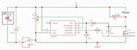
Any suggestions on how to reduce the resistance of the attached circuit.

A supercapacitor (EDLC) is used to power a small motor. There is an ATTiny85 chip in the circuit that is used as a timer and a PWM controller for the motor. The problem that I'm loosing about half a volt between the capacitor's voltage and the voltage across the motor's leads. I need to minimize losses in the circuit as much as possible.

Can you suggest means to reduce voltage loses to the motor?
 

Attachments

  • PWM Circuit.jpg
    PWM Circuit.jpg
    84.8 KB · Views: 188
There are good reasons for that, a capacitor makes a pretty poor battery.
Under some/most conditions, I agree with you, but in other cases, a battery makes a pretty poor power supply. As a free flight power source, batteries are heavy and take time to recharge. Capacitor are much lighter and re-charge within seconds.
 
For those of you who question the use of a capacitor, the entire driving force behind this project is to make a device/circuit that will make a capacitor preform like a battery. Why? Because no one has done it.

Actually, lotsa people have done it. Ultracaps are common on hybrid city busses, and Coleman (the camping lantern people) used to make a cordless screw driver that used caps instead of nicad cells.

ak
 
Under some/most conditions, I agree with you, but in other cases, a battery makes a pretty poor power supply. As a free flight power source, batteries are heavy and take time to recharge. Capacitor are much lighter and re-charge within seconds.
They are lighter, and charge faster, mostly because they are much lower capacity - and to charge quickly requires large charging currents. It's simple physics - to charge faster needs higher current - to put hours of charge in a storage medium in seconds takes massive currents. For example, if a battery takes 5 hours to charge at 1A, a similar specification (if such existed) capacitor would need 60A to charge in 5 minutes, or 300A to charge in just one minute.
 
The difference between the two is about half a volt.
You shouldn't be losing 1/2 Volt if the current is 3A. There must be a poor connection or else the wire cross-section is too small.
 
Ok, you lost the dummy again. "Measure V loo\sr" ??? Capacitor voltage is measured across the cap leads, motor voltage is across the motor leads. The difference between the two is about half a volt.
Meaure Voltage loss, where the drops occur, what path element creates the loss ?
 
Meaure Voltage loss, where the drops occur, what path element creates the loss ?
To be even clearer, measure the voltage directly from the negative pin of C3 to the negative pin on the motor - this will give you the losses in the negative side. Then measure the voltage directly from the positive pin of C3 to the positive pin of the motor, this will give you the loss on the positive side. The two added together give the total loss, but more importantly it shows which side you're making the main loss on - presumably the negative side?.
 
Nigel, danadak and alec-t, you have all made good suggestions.

Let me think out loud for a bit.

There are only four elements in the motor loop; the motor, the capacitor, the FET and a switch. The motor in this case is pretty well fixed, can’t be changed. It’s resistance is 0.72 ohms. ESR of the LIC can be pretty high. The 100F capacitor I’m using in testing has an ESR of 0.080 ohms. I can lower that somewhat by using a bigger capacitor but it is still going to be around 0.06 ohms. The switch could be a major resistance. I haven’t measured the resistance of the switch but I have modified the circuit to double the switch contact points. That ought to reduce its resistance to what it was. I’ve done nothing about measuring the resistance of the FET. I wasn’t sure how to go about it until Nigel’s last post.

Anything wrong in my thinking?

Give me about a week and I will get back with what I’ve found out.
 
Nigel, danadak and alec-t, you have all made good suggestions.

Let me think out loud for a bit.

There are only four elements in the motor loop; the motor, the capacitor, the FET and a switch. The motor in this case is pretty well fixed, can’t be changed. It’s resistance is 0.72 ohms. ESR of the LIC can be pretty high. The 100F capacitor I’m using in testing has an ESR of 0.080 ohms. I can lower that somewhat by using a bigger capacitor but it is still going to be around 0.06 ohms. The switch could be a major resistance. I haven’t measured the resistance of the switch but I have modified the circuit to double the switch contact points. That ought to reduce its resistance to what it was. I’ve done nothing about measuring the resistance of the FET. I wasn’t sure how to go about it until Nigel’s last post.

Anything wrong in my thinking?

Yes, don't measure the resistance - measure the voltage drop across the points I suggested.

I would hazard a guess that the FET isn't been switched on properly, so you're making too much loss across it.
 
Yes, don't measure the resistance - measure the voltage drop across the points I suggested.
Sorry, I misspoke. I meant measure the voltage to determine areas of high resistivity. Isn't a voltage drop indicator of resistance?

Earlier there was mention of "a proper driver - and probably a SM circuit" I'm sorry, these are above my present electronics knowledge and abilities. And, no, I do not want someone to design them for me.
 
Sorry, I misspoke. I meant measure the voltage to determine areas of high resistivity. Isn't a voltage drop indicator of resistance?
Yes, but it's far easier and much more accurate to measure the voltage drop - and it's the voltage drop you need to know, not the resistance, so you'd have to also measure the current and calculate the voltage drop anyway
 
Sorry, I misspoke. I meant measure the voltage to determine areas of high resistivity. Isn't a voltage drop indicator of resistance?

In a series loop of elements you can do it either way, both will reveal the problem area, give you a
good feel for the largest, and smallest, offender in the scheme of things. V is a little better as you can have
your circuit powered up under operating conditions and do the measurements without disturbing the
circuit. Devices in operation will show a more complete picture as their terminal V's may/usually will
show different results then when not powered.


Regards, Dana.

Except you need more specialised equipment to measure the resistance, as a conventional multi-meter doesn't go low enough on ohms ranges, and you can't measure the most likely issue - the resistance of the FET.
 
My $ 12 meters goes to 10 mohm. Same meter good to 100 uV. But yes
we can always use more accurate test gear. I do have equipment to fA,
nV, not often used.

Op states his concern is .5V, and I gather motor is at 3A, so effective R
problem is ~ 166 mOhms distributed across the power loop. So to your
point he should check how low his R meter goes, although doing this in V
is more accurate as a troubleshooting problem, and done at operational
system voltages.

In this case V's rule, Ohms suck, as a diagnostic tool. Note to do the MOSFET
of course he has to slow PWM way down to get Vrdson unless its has S/H
and averaging, many meters do not have.


Regards, Dana.
 
I hang my head in shame.

After declaring earlier that I didn't need help reading a data sheet, I need help understanding what I'm reading.

I'm looking at the DMN2040 data sheet and trying to determine if there might be a better FET for the job. In the Electrical Characteristics table, there is a characteristic named 'Diode Forward Voltage.' I don't know is the significance this characteristic. I understand that it is a source-drain voltage. But what does that characteristic (parameter) tell me about the FET? Is a high number good, or bad? Or should it be a high number for certain applications and low for others?

We are still trying to narrow down the source of the lost voltage in the circuit. Right now, we are investigating the possibility that the loss voltage is the results of the ATtiny85 coding. Progress is slow because of involvement with a school's robotics program.
 

Attachments

  • DMN2040U-1360765.pdf
    477.6 KB · Views: 13
We are still trying to narrow down the source of the lost voltage in the circuit. Right now, we are investigating the possibility that the loss voltage is the results of the ATtiny85 coding.

I refer you to post #28, which clearly explains exactly how simple (and quick) it is to measure the losses, and where they are.

You should do this at full power, i.e. with the FET permanently switched ON, and not pulsing.

Have you never spent the few seconds measuring those voltages?.
 
I refer you to post #28, which clearly explains exactly how simple (and quick) it is to measure the losses, and where they are.

Have you never spent the few seconds measuring those voltages?
Doing it exactly as per post #28 leaves us 0.2v short of what it should be. That is why we are investigating the code to see if there is anything in it that limits the FET being fully open, flowing current.

Your last comment was not called for. Nor should it be allowed in a forum posting. The forum is not a place where you can put folks down, or make fun of, be derogatory towards anyone for any reason.
 
Your last comment was not called for. Nor should it be allowed in a forum posting. The forum is not a place where you can put folks down, or make fun of, be derogatory towards anyone for any reason.
It was not a put down, it was an expression of exasperation.
- You show up claiming you are a "complete know-nothing"
I'm a complete know-nothing when it comes to electronics.
- You ask a bunch of questions,
- We ask what level of help you need
- You get offended and claim you know more than "nothing"
Then
- You get offended when someone expects some level of competence.

Please. Feelings shouldn't be so easily hurt.
 

New Articles From Microcontroller Tips

Back
Top