Continue to Site

Welcome to our site!

Electro Tech is an online community (with over 170,000 members) who enjoy talking about and building electronic circuits, projects and gadgets. To participate you need to register. Registration is free. Click here to register now.

  • Welcome to our site! Electro Tech is an online community (with over 170,000 members) who enjoy talking about and building electronic circuits, projects and gadgets. To participate you need to register. Registration is free. Click here to register now.

help in identifying component

Status
Not open for further replies.
OK, there is something drastically wrong with the basic power circuit then...

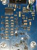
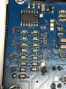
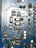
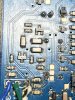
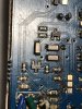
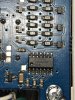
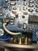
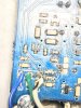
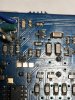
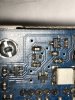
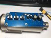
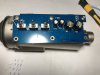
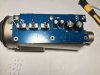
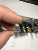
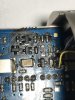
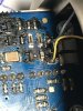
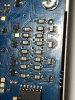
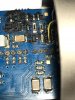
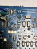
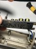
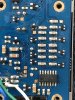
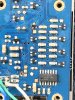
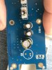
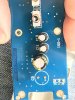
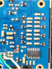
Can you take a few more photos of the circuit board - each side as three or four overlapping parts and try to get the detail sharp enough to read the numbers on the resistors etc?

I'm going to try to draw out part of the circuit to figure out how it should work, if I can see the components clearly enough.
 
ok, i will do it, i really appreciate a lot your help, i will upload the picture tomorrow, today its a little late here in germany, and all the stuff are in the basement, and now its to cold to go there today.
 
pls sorry if i brake some rule but i need to upload many picure
 

Attachments

  • IMG_6889-min.JPG
    IMG_6889-min.JPG
    881.5 KB · Views: 219
  • IMG_6890-min.JPG
    IMG_6890-min.JPG
    933.7 KB · Views: 219
  • IMG_6891-min.JPG
    IMG_6891-min.JPG
    934.3 KB · Views: 217
  • IMG_6892-min.JPG
    IMG_6892-min.JPG
    915.9 KB · Views: 222
  • IMG_6893-min.JPG
    IMG_6893-min.JPG
    759.7 KB · Views: 219
  • IMG_6894-min.JPG
    IMG_6894-min.JPG
    863.6 KB · Views: 227
  • IMG_6899-min.JPG
    IMG_6899-min.JPG
    884.6 KB · Views: 225
  • IMG_6900-min.JPG
    IMG_6900-min.JPG
    587.1 KB · Views: 214
  • IMG_6901-min.JPG
    IMG_6901-min.JPG
    794.1 KB · Views: 211
  • IMG_6902-min.JPG
    IMG_6902-min.JPG
    1 MB · Views: 220
  • IMG_6903-min.JPG
    IMG_6903-min.JPG
    821.3 KB · Views: 209
  • IMG_6904-min.JPG
    IMG_6904-min.JPG
    880.6 KB · Views: 209
  • IMG_6900-min.JPG
    IMG_6900-min.JPG
    587.1 KB · Views: 218
  • IMG_6901-min.JPG
    IMG_6901-min.JPG
    794.1 KB · Views: 201
  • IMG_6902-min.JPG
    IMG_6902-min.JPG
    1 MB · Views: 206
  • IMG_6903-min.JPG
    IMG_6903-min.JPG
    821.3 KB · Views: 206
  • IMG_6904-min.JPG
    IMG_6904-min.JPG
    880.6 KB · Views: 204
  • IMG_6905-min.JPG
    IMG_6905-min.JPG
    873.6 KB · Views: 211
  • IMG_6908-min.JPG
    IMG_6908-min.JPG
    637.7 KB · Views: 206
  • IMG_6909-min.JPG
    IMG_6909-min.JPG
    710.6 KB · Views: 204
  • IMG_6910-min.JPG
    IMG_6910-min.JPG
    1 MB · Views: 204
  • IMG_6911-min.JPG
    IMG_6911-min.JPG
    1 MB · Views: 207
  • IMG_6912-min.JPG
    IMG_6912-min.JPG
    989.1 KB · Views: 210
i hope all this picture work
 

Attachments

  • IMG_6925-min.JPG
    IMG_6925-min.JPG
    689.8 KB · Views: 208
  • IMG_6926-min.JPG
    IMG_6926-min.JPG
    717 KB · Views: 204
  • IMG_6927-min.JPG
    IMG_6927-min.JPG
    772.4 KB · Views: 208
  • IMG_6928-min.JPG
    IMG_6928-min.JPG
    722.2 KB · Views: 217
  • IMG_6929-min.JPG
    IMG_6929-min.JPG
    569.6 KB · Views: 205
  • IMG_6930-min.JPG
    IMG_6930-min.JPG
    274.5 KB · Views: 202
  • IMG_6917-min.JPG
    IMG_6917-min.JPG
    896.5 KB · Views: 212
  • IMG_6918-min.JPG
    IMG_6918-min.JPG
    757 KB · Views: 235
  • IMG_6919-min.JPG
    IMG_6919-min.JPG
    745.8 KB · Views: 202
  • IMG_6920-min.JPG
    IMG_6920-min.JPG
    607.8 KB · Views: 196
  • IMG_6921-min.JPG
    IMG_6921-min.JPG
    614.8 KB · Views: 207
  • IMG_6922-min.JPG
    IMG_6922-min.JPG
    640.1 KB · Views: 200
  • IMG_6895-min.JPG
    IMG_6895-min.JPG
    853.3 KB · Views: 199
  • IMG_6896-min.JPG
    IMG_6896-min.JPG
    824 KB · Views: 205
  • IMG_6897-min.JPG
    IMG_6897-min.JPG
    823.2 KB · Views: 197
  • IMG_6898-min.JPG
    IMG_6898-min.JPG
    857.8 KB · Views: 203
  • IMG_6907-min.JPG
    IMG_6907-min.JPG
    637 KB · Views: 204
  • IMG_6908-min.JPG
    IMG_6908-min.JPG
    637.7 KB · Views: 203
  • IMG_6906-min.JPG
    IMG_6906-min.JPG
    811 KB · Views: 198
  • IMG_6907-min.JPG
    IMG_6907-min.JPG
    637 KB · Views: 201
  • IMG_6915-min.JPG
    IMG_6915-min.JPG
    803.5 KB · Views: 204
  • IMG_6916-min.JPG
    IMG_6916-min.JPG
    691.1 KB · Views: 214
  • IMG_6923-min.JPG
    IMG_6923-min.JPG
    707.1 KB · Views: 206
  • IMG_6924-min.JPG
    IMG_6924-min.JPG
    1,000.7 KB · Views: 196
  • IMG_6905-min.JPG
    IMG_6905-min.JPG
    873.6 KB · Views: 208
  • IMG_6906-min.JPG
    IMG_6906-min.JPG
    811 KB · Views: 193
  • IMG_6913-min.JPG
    IMG_6913-min.JPG
    995 KB · Views: 192
  • IMG_6914-min.JPG
    IMG_6914-min.JPG
    907 KB · Views: 200
  • IMG_6931-min.JPG
    IMG_6931-min.JPG
    448.7 KB · Views: 203
  • IMG_6932-min.JPG
    IMG_6932-min.JPG
    554.8 KB · Views: 208
I think that covers it for photo detail!

What voltages do you get on the three square gold pads in a group between the XLR wires and IC? They are test points in the power circuit.
 
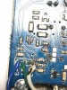
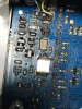
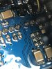
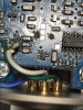
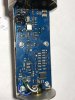
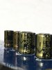
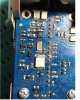
OK; remove the large electrolytic cap from the other side of the board, the same size as the one behind those gold pads but higher up - then re-check the voltages?

There is a short circuit to ground somewhere in that area.
 
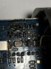
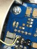
The capacitor is still in place in that photo?
If you have removed it, please take a photo of the topside of the PCB, centred on where it was; there are through VIA holes underneath it.
 
sorry, use an old image to modify it, but I measured the voltage without the capacitor on
 

Attachments

  • IMG_6933.JPG
    IMG_6933.JPG
    1.3 MB · Views: 207
  • IMG_6934.JPG
    IMG_6934.JPG
    1.4 MB · Views: 212
  • IMG_6935.JPG
    IMG_6935.JPG
    890.7 KB · Views: 204
  • IMG_6936.JPG
    IMG_6936.JPG
    1.1 MB · Views: 197
Sorry, wrong cap - I intended for you to remove the other large one..

Leave that one out as well though, for now.
 
ok, i use the old picture to write the voltage, but i already took the cap
 

Attachments

  • Sin título1.png
    Sin título1.png
    1.6 MB · Views: 204
  • ultima.jpg
    ultima.jpg
    99.2 KB · Views: 189
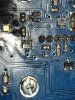
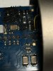
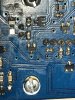
OK, it looks like the connection from the positive of that cap goes up the topside and out between the other two caps.
It then continues up the edge of the board & under the black stuff, with a branch.

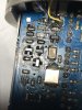
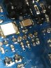
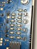
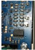
See the yellow arrows on this photo. Check the voltage on that resistor.


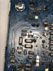
However, looking at the earlier photo with voltages marked, I just noticed the one for the IC pin 14, which is the lowest of all. :banghead:
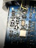
That may mean it is the cap or device next to it, possibly a zener in a three terminal package?

The Y4W marking seems to make it a 15V zener, such as this:

Without connecting to power, check resistance from pin 14 to pin 7 - then remove that Y4W device and check again?
If it's then not shorted, fit a new 15V zener!

If the short is still present it must be the IC or capacitor, from what I can see..


IMG_6924-min.JPG
 
resistance 7 and 14 it's 5.004Mohm that its without taking out any components, can you pls show me wicht component i have to take out
 
OK, that's a false lead then... It must be fed via a transistor or diode and there is just not enough voltage present for that to conduct

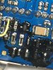
It does appear to be a short somewhere around the area that had the black coating, as the voltages there are very low, lower than anywhere else that has a power connection.

Can you confirm that the yellow marked trace does connect through to the centre of the group of three gold pads? That's where I think it feeds from, but it's better to confirm it.
 
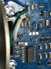
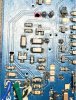
Another suggestion - try scrubbing the entire board with a small stiff brush - eg. an old toothbrush - and isopropyl alcohol.
There is a lot of flux residue around some components and I can see fragments of loose solder in some photos.
 
Status
Not open for further replies.

Latest threads

New Articles From Microcontroller Tips

Back
Top