Continue to Site

Welcome to our site!

Electro Tech is an online community (with over 170,000 members) who enjoy talking about and building electronic circuits, projects and gadgets. To participate you need to register. Registration is free. Click here to register now.

  • Welcome to our site! Electro Tech is an online community (with over 170,000 members) who enjoy talking about and building electronic circuits, projects and gadgets. To participate you need to register. Registration is free. Click here to register now.

help in identifying component

Status
Not open for further replies.
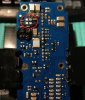
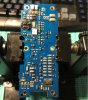
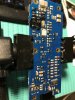
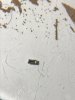
This component that belongs to a RODE NTA2 condenser microphone, unfortunately it does not work anymore, and I sent it to be repaired in the RODE technical service, and its answer was that the Mainboard has to be changed, the problem is that the mainboard costs € 38 but with the The total workforce is € 201, that is an exaggeration of price, so I would like to repair it, ahh forget to mention that they do not sell the parts to repair the microphone by oneself.

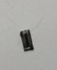
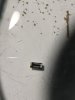
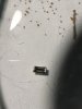
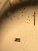
they are two equal components, they look like a capacitor but it has a black line in the middle, with the multimeter I measured it in capacitance, resistance, diode, continuity and I don't get any measurement. and I really have no idea what component it is and also what value it has
 

Attachments

  • IMG_688011.jpg
    IMG_688011.jpg
    18.9 KB · Views: 301
  • IMG_6882.JPG
    IMG_6882.JPG
    167.8 KB · Views: 312
  • IMG_6883.JPG
    IMG_6883.JPG
    187.8 KB · Views: 349
  • IMG_6884.JPG
    IMG_6884.JPG
    199.6 KB · Views: 264
120848
 

Attachments

  • IMG_6885.JPG
    IMG_6885.JPG
    773.1 KB · Views: 239
  • IMG_6886.JPG
    IMG_6886.JPG
    684 KB · Views: 243
  • IMG_6887.JPG
    IMG_6887.JPG
    723 KB · Views: 214
  • IMG_6888.JPG
    IMG_6888.JPG
    601.2 KB · Views: 248
They are probably the capsule bias resistors - one gigohm or thereabouts, in a typical condenser mic.

You won't get sensible readings with most multimeters, they will read open circuit.
 
I cannot find a schematic for the NT2A, but here is one for the NT2:

R31 & R32 are the two 1G Ohm resistors, in that one.

I'd suspect the audio part is likely fairly similar, but yours has a CMOS IC as well - I'm guessing that is the oscillator and driver for the high voltage generator, with the IC and parts at the lower right quadrant of the PCB being the power section, replacing the lower left part of the schematic.
 

in this page its the schematic, i already register, but still waiting for the administrator aprovation, and that was 3 days ago so, is someone here its member can download and upload here pls
 
Some posts relating to that exact fault say it's often cured just be re-flowing all the soldered joints on the circuit board.
(ie. heat each joint and apply a very small extra amount of flux cored solder).
 
yes, i already read about that, but i don't know if its the best way to repair, but at the end i will do it tomorrow, its a 250€ mic and i want to fix it
 
yes, i already read about that, but i don't know if its the best way to repair, but at the end i will do it tomorrow, its a 250€ mic and i want to fix it
You're been given good advise. I would listen if I were you. Members here try VERY hard to help.
ETO is not about guessing. Like other forums out there.
 
We're a small but proud forum. Cause WE know stuff. And we have pros here that don't just jabber senseless advice.
 
One question, I saw a video of a man who checks the ic with the multimeter in diode mode, basically the red clamp of the multimeter on the negative leg of the ic and the negative on each of the legs of the ic, and today I made that test on the CD40106 ic, and on all legs except number 9, could the ic be damaged?

this ist the datasheet

 
What are the voltages on the two points I've marked, relative to the XLR ground pin? There should be tens of volts on one or both.
If there is, the IC is OK.

It does not have to have the capsule connected for this, if it is presently detached - just the XLR side with phantom power.


IMG_6883a.jpg
 
Status
Not open for further replies.

Latest threads

New Articles From Microcontroller Tips

Back
Top