Continue to Site

Welcome to our site!

Electro Tech is an online community (with over 170,000 members) who enjoy talking about and building electronic circuits, projects and gadgets. To participate you need to register. Registration is free. Click here to register now.

  • Welcome to our site! Electro Tech is an online community (with over 170,000 members) who enjoy talking about and building electronic circuits, projects and gadgets. To participate you need to register. Registration is free. Click here to register now.

Help Identifying component on circuit board

Status
Not open for further replies.

Pete44904

New Member
Hope someone can help me as I'm trying to identify the two black components in front of the 3 large capacitors in the below picture as to me the first one looks to be damaged any help would be greatly appreciated.

20220223_212751.jpg


Thanks
 

Attachments

  • 20220223_212751.jpg
    20220223_212751.jpg
    995.7 KB · Views: 199
Is there a reference designator labeled on the PCB ?

What device does this PCB belongs to ?

Also, please take a couple of additional photos.
  • Perpendicular to the PCB/unknown components.
  • bottom at the PCB (also perpendicular to the pcb).
 
Ferrite choke jumper.
To be bad, its wire would have to be open-circuited or the black core material cracked.

Search for "jumper inductor" too
 
Thanks for replying I really appreciate it, the board is from an old Acorn Electron Plus 3 which won't turn on my gut feeling is it's the capacitors as they are nearly 30 years old but just wanted to check what these two black things were as wondered if they had been damaged as one was discoloured. Have included a few more pics of the board as on checking the bottom of the board there are a few marks.

Worst case if all else looks ok will start replacing the 30 year old capacitors.

Again thanks for all your help I really do appreciate it.
20220224_172602.jpg


20220224_172548.jpg

20220224_172531.jpg
 
I would apply +/- 5V (or whatever needs) from an external supply to the rails and check if anything heats up or works. Then you can suspect its on-board supply or a component failure. Or lift the ferrite links and confirm if its supply alone works without the circuitry load.
 
Thanks for replying I really appreciate it, the board is from an old Acorn Electron Plus 3 which won't turn on my gut feeling is it's the capacitors as they are nearly 30 years old but just wanted to check what these two black things were as wondered if they had been damaged as one was discoloured. Have included a few more pics of the board as on checking the bottom of the board there are a few marks.

Worst case if all else looks ok will start replacing the 30 year old capacitors.

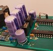
Beautiful clean board for 30 years old :D

Randomly changing parts is never a good way of trying to find a fault, an ESR meter on the capacitors would be a better idea - but not much use if you don't have one.

For a start you might try testing the two secondary rectifiers (the little round ones), as it's simple and non-invasive, you can read them in-circuit with the diode test range of a meter - if either are faulty it will read S/C (it's a fairly common fault on SMPSU's).

If not, then see if there's any DC voltage on the positives of those diodes (with respect to chassis), if it's low or pulsing it's more likely to be a capacitor issue.

Failing that, measure the voltage across the big capacitors at the top, there should be about 340V across those - if there is?, then check for voltage to the UC3524 chip, negative pin is pin 8, positive pin is pin 15, and the datasheet says a minimum of 8V and a maximum of 40V. If there's no voltage (or less than 8V) then there may be failed start-up resistors, which will probably feed pin 15 to start the supply.

The datasheet is rather vague, and only seems to give low voltage applications.
 
Status
Not open for further replies.

Latest threads

New Articles From Microcontroller Tips

Back
Top