Continue to Site

Welcome to our site!

Electro Tech is an online community (with over 170,000 members) who enjoy talking about and building electronic circuits, projects and gadgets. To participate you need to register. Registration is free. Click here to register now.

  • Welcome to our site! Electro Tech is an online community (with over 170,000 members) who enjoy talking about and building electronic circuits, projects and gadgets. To participate you need to register. Registration is free. Click here to register now.

Help identifying capacitor

Status
Not open for further replies.

Mishaua

New Member
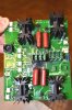
I have a power controller board for a tire balancing machine that the capacitor failed causing a surge and destruction of a resistor. I need some help identifying what capacitor it can be replaced with. Also I want to replace the blown surface mount resistor with a standard resistor. The damaged one had a number of 200 on it. Does this mean I should be able to replace it with a 200 ohm resistor, or is there some other variables I need to consider? Attached are some images of the board and capacitor.**broken link removed** **broken link removed**
 
hi,
The PCB looks like a full bridge, so I would say that the resistor is 200R, the four caps look the same and are marked 104 that's a 0.1uF at 630V working voltage.

Your main problem will be clearing the carbonised burn on the PCB, its most likely conductive.

E
 

Attachments

  • DSC_0009.jpg
    DSC_0009.jpg
    225.4 KB · Views: 275
I wasn't aware that carbon was conductive. Thanks for the info. This board is pretty simple and only has traces on the top and bottom layer. I will just probably cut out the burned pieces where they might connect and test for continuity. Should I be worried about the resistor wattage? Also any idea on what the P and J stand for in p104j? I plan to just replace the caps and install the new capacitor on this side.**broken link removed**
 
hi D,
Checking the data sheet it states that NOT suitable for mains applications, refer image.
It must be an 'X' rated capacitor.

E
 

Attachments

  • A001.gif
    A001.gif
    24.1 KB · Views: 283
This looks like the closest thing is https://www.mouser.com/ProductDetai...EpiMZZMv1cc3ydrPrF%2bfZ13WJ/r1//%2bb7UvCkwxQ= but it doesn't say if they are 'X' rated. Do you think it would work? There are some similar ones on amazon https://www.amazon.com/CBB22-0-1uF-Metallized-Polypropylene-Capacitors/dp/B005X2HC56 but I would rather buy a Panasonic branded one instead of some Chinese mystery brand. Also would this resistor work? https://www.mouser.com/ProductDetai...=sGAEpiMZZMu61qfTUdNhG3gu04FpCMicnC2Lvp02hes=
 
hi,
I would assume that the voltage rating of the old cap, marked as 630V is the DC rating, this would indicate a AC RMS rating of 310Vac, which is typical for a 230Vac mains supply.
I would use the type shown in this image.

You may have to lengthen the leads of the new cap in order to use the existing holes.
E
 

Attachments

  • A003.gif
    A003.gif
    15.2 KB · Views: 260
the J is +-5%

The SMT resistor marked 200 is more likely to be 20 ohms just like those marked 430 are likely to be 43 ohms. Check one.

Typo: fixed 43 to 430
 
Last edited:
the J is +-5%
The SMT resistor marked 200 is more likely to be 20 ohms just like those marked 430 are likely to be 43 ohms. Check one.
Good catch. I checked it and it is 20 ohm.
hi,
I would assume that the voltage rating of the old cap, marked as 630V is the DC rating, this would indicate a AC RMS rating of 310Vac, which is typical for a 230Vac mains supply.
I would use the type shown in this image.

You may have to lengthen the leads of the new cap in order to use the existing holes.
E

Thank you guys for your help I ordered the capacitors that ericgibbs suggested, and used a 20 ohm 1 watt resistor (I used some smd sizing chart I found online to come up with the wattage). In the process of verifying the resistors, I discovered that another one was dead . I replaced the 4 caps, the burned out resistor, and the second 20ohm resistor right next to it and everything works now. Just as an FYI for anyone that might search this thread in the future, this was a motor control board for a Coats 1050 solid state wheel balancing machine.
 
Status
Not open for further replies.

Latest threads

New Articles From Microcontroller Tips

Back
Top