Electro Tech is an online community (with over 170,000 members) who enjoy talking about and building electronic circuits, projects and gadgets. To participate you need to register. Registration is free. Click here to register now.
Welcome to our site! Electro Tech is an online community (with over 170,000 members) who enjoy talking about and building electronic circuits, projects and gadgets. To participate you need to register. Registration is free. Click here to register now.
it would be more helpful if you could let us know what device it was in and, even more helpful, show the circuit.
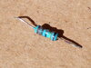
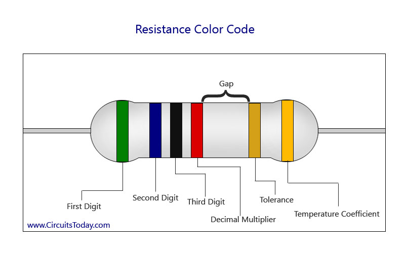
my first guess is a red, black, black, yellow (plus a tolerance color). So, 2M. Or Brown, black, black, yellow (1M). However, it is unlikely to see so much damage on such a high value resistor unless it is used In some high voltage device or damaged by a lightning strike.
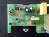
Thank you. I don't have a circuit diagram but its from a 220v 3kw patio heater with 3 power settings and remote control. The resistor goes between the 1n4007 diode and blue capacitor near the top right of the board. One end goes to the microchip (KW618C or KB6228201) and the other to the right lead of the blue capacitor. Top and bottom pics of the board attached.
It appears to be feeding zero-crossing pulses to the chip?, so is likely to be a high value resistor - so 1Meg is probably about right, assuming the colours haven't changed (and they often do).
As it's a high value, are you sure it's O/C? - did you test it on a high enough range?.
Thanks for everyone's help here. The resistor was open, and burnt quite badly so colours were not true. I thought it might be 100 ohms but after all the feedback it seems that 1 meg is the right choice. I'll try it today. Many thanks again to everyone, its appreciated.
Thanks for everyone's help here. The resistor was open, and burnt quite badly so colours were not true. I thought it might be 100 ohms but after all the feedback it seems that 1 meg is the right choice. I'll try it today. Many thanks again to everyone, its appreciated.
But the thought occurs to me that resistors also have a voltage rating, and that resistor will have been subjected to mains voltage for long periods.
It seems reasonable that overvolt operation will eventually result in failure.
But the thought occurs to me that resistors also have a voltage rating, and that resistor will have been subjected to mains voltage for long periods.
It seems reasonable that overvolt operation will eventually result in failure.
Resistors do have voltage ratings - and historically resistors in such circuits do go O/C, but they don't generally 'burn up' as there's not enough power dissipated in them.
Most common failures in such circuits was due to putting two smaller resistors in series, and these VERY commonly fail (it's one of the common design flaws), I don't know if it's down to voltage ratings, or just poor voltage sharing across the resistors - but removing the two in series, and replacing with a single higher wattage resistor, means they never fail again. It's worth mentioning that a 1W resistor usually has a higher voltage rating than a 1/2 W one.
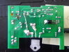
Looking at the picture of the component side in post #3 it looks like more components have also failed. I have traced out part if the circuit. The power supply uses the yellow capacitor in the top right hand corner to drop the voltage for the electronics. It lookes like the discharge resistor in parallel with this capacitor has also failed. The fuse and the 47 ohm resistor in series with this capacitor have also been removed so I assume that these have also failed. The smaller yellow capacitor and the blue varistor are directly across the mains after the fuse. The fact that the varistor looks to be undamaged seems to rule out a severe high voltage transient on the mains as being the cause of the problem. Some history of the problem would be helpful. For example could there gave been a buildup of dirt on the board that has caused a flashover.
Basically there was a loud pop while the heater was on and a number of components cooked. The resister in question was burnt and open as was the 47 ohm 2w resistor plus the fuse and a land pattern that has a wire across it now. Anyway I replaced everything I thought was bad but when i connected it up the resister in question (1 meg) starting smoking so I turned it off. Obviously there is more wrong with the board so I may just give up and connect the heater to an on off switch. First time I have used this forum and I find the helpfulness of everyone is fantastic.
I agree that if the resistor was 1 meg then it should not overheat as it would only be dissipating 62.5 mW even with 250 volts across it. I think the device on the etch side of the board is an infra red receiver for a remote control. I think the 8 pin IC is a special function device to interpret the infra red signal and control the drive to the triac. Eith the information in post #13 about the blown track I think the large yellow capacitor first failed short circuit. this would cause one of the 1N4007 diodes to fail short circuit so the mains was then short circuited via the 47 ohm resistor which blew the track and the 47 ohm resistor. I think the TS's solution of replacing the board with a switch is the most practical solution.
Well I have just replaced the board with a switch and all if fine - but now I am thinking of designing my own circuit to replace the lost remote control for power switching. I think I'll have a go at s similar circuit with triac to control the power using input from an arduino or esp8266 with wifi so I can control it from my phone.
Actually what I have done for the moment is ditch the circuit board and wired in a Shelly1 so I can control the on/off remotely from my phone, but it doesn't provide for the 3kw power level switching, thus the idea in my last post.
This site uses cookies to help personalise content, tailor your experience and to keep you logged in if you register.
By continuing to use this site, you are consenting to our use of cookies.