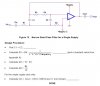
Hello everyone. I am trying to implement a band-pass circuit with a narrow passband at 10kHz on breadboard and for some reason I can't get it to work. I am using the design procedure outlined in pages 6-7 in the following Texas Instruments pdf:
Filter Design in Thirty Seconds
This can be seen in the attachment as well.
I went through the simple design procedure and used C1=C2=0.01 microfarards (non-polarized). Then I went through and calculated the R values. Then finally for Cin and Cout I am using 1 microfarard (non-polarized).
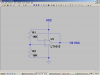
I simulated the circuit and it worked out in PSPICE.
However, it does not work when I hook it up. I use a 741 and hook up the circuit as shown. For Cin and Cout I use non-polarized capacitors if that matters. At the input I hooked up a function generator and hooked up an oscilloscope at the output. I adjusted the function generator's output level to a 2.5V amplitude square wave. I then adjusted the frequency from around 100Hz to 11kHz and the output waveform on the oscilloscope didn't change much. The output just looks very noisy at all frequencies and the signal amplitude remains small for all frequencies. Some times I noticed that the signal keeps getting smaller as time goes by until it gets to zero.
To my understanding the signal should be about zero for any input frequency outside the filter bandwidth and should pass through a relatively undistorted squarewave signal at the passband.
I know this is not much description of the problem, but if anyone can think of any advice I'd appreciate it.
Thanks.
Filter Design in Thirty Seconds
This can be seen in the attachment as well.
I went through the simple design procedure and used C1=C2=0.01 microfarards (non-polarized). Then I went through and calculated the R values. Then finally for Cin and Cout I am using 1 microfarard (non-polarized).
I simulated the circuit and it worked out in PSPICE.
However, it does not work when I hook it up. I use a 741 and hook up the circuit as shown. For Cin and Cout I use non-polarized capacitors if that matters. At the input I hooked up a function generator and hooked up an oscilloscope at the output. I adjusted the function generator's output level to a 2.5V amplitude square wave. I then adjusted the frequency from around 100Hz to 11kHz and the output waveform on the oscilloscope didn't change much. The output just looks very noisy at all frequencies and the signal amplitude remains small for all frequencies. Some times I noticed that the signal keeps getting smaller as time goes by until it gets to zero.
To my understanding the signal should be about zero for any input frequency outside the filter bandwidth and should pass through a relatively undistorted squarewave signal at the passband.
I know this is not much description of the problem, but if anyone can think of any advice I'd appreciate it.
Thanks.