Continue to Site

Welcome to our site!

Electro Tech is an online community (with over 170,000 members) who enjoy talking about and building electronic circuits, projects and gadgets. To participate you need to register. Registration is free. Click here to register now.

  • Welcome to our site! Electro Tech is an online community (with over 170,000 members) who enjoy talking about and building electronic circuits, projects and gadgets. To participate you need to register. Registration is free. Click here to register now.

Help: electrical circuit for powering magnet with 12v power supply

Status
Not open for further replies.

aijak

New Member
Hello everybody,

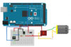
I am trying to power a solenoid magnetic coil with a 12 v battery supply that is regulated by Arduino digital pin. I am using a N-MOSFET TO247AC however my current circuit overheats the composition. New to electronics I am not sure wether I have it wrongly wired or possibly using the wrong type of MOSFET.

A look at the diagram and any suggestions would be very welcome!

Best,

Aija
 

Attachments

  • Screenshot 2020-03-28 at 11.48.16.png
    Screenshot 2020-03-28 at 11.48.16.png
    183.3 KB · Views: 232
Welome to ETO!
TO247AC is the transistor package type, not the MOSFET type. Importantly, which MOSFET are you using?
What do you mean by 'composition'?
What is the DC resistance of the coil?
How rapidly are you trying to switch it on/off?
 
TO247AC is the transistor package type, not the MOSFET type. Importantly, which MOSFET are you using?
Aha, it makes sense now. So I'm not using a MOSFET at all. Would TIP22 be a more applicable component?

Composition = circuit

I'm not sure if I'm able to calculate the DC resistance of the coil, is it very relevant?

The code running through Arduino switches on and off every few seconds, it can be regulated though.

Thanks.
 
My apologies if the answers were unclear. I am unable to determine the DC resistance of the coil, by composition I ment the circuit itself = it overheats. The code runs every few (approximately 3/4) seconds on/off. With the MOSFET type I'm having problems,
 
It was my understanding that TO247AC is a N channel MOSFET. If that's not the case then I'm not using a MOSFET at all.
 
TO247AC is a package style, just like TO220 and SOIC-8 are.
You need to provide the information which is marked on the package....
 
Those are specs, not the device part number.
 
That MOSFET looks good for the job. If it happens to have a Vgs threshold at the 4V end of its specified range and the current through it is more than a few Amps (which we don't know, since you can't state the coil resistance) then expect it to get hot. Breadboards are not designed to handle several Amps, though, so perhaps heat is being generated in the breadboard's conductive strips too.
 
It is worse than overheating, it exploded. I'm not sure if breadboard's strips can generate so much heat...
 
I ment the circuit itself = it overheats. The code runs every few (approximately 3/4) seconds on/off.

You should look into a dedicated solenoid driver. The system may be more reliable in the long run. Generally, you kick it and then reduce the voltage. Don;t know what the application is.
 
Are you running the arduino at 5V?
You need a logic level mosfet, the IRL540 may be suitable but it depends on the solenoid.
You could also use a mosfet driver but that requires another chip.
Do you have a flyback diode across the solenoid?
Do you have a link to the solenoid or a picture?

Mike.
Something like this might be an easier solution. Note that price is for three - so less than $1 each.
 
You need a logic level mosfet
Was thinking the same thing, because there is no Vgs=5V in the Rds parameter:
IRFP3206.png

If the MOSFET is not fully turned on, i.e. the gate voltage is between Vgs(th) and 10V, it's generating heat, correct?
 
Not sure why you can't determine the coil resistance, but if it is an AC version then that is the cause of the problem, very low resistance.
Max.
 
Right, thanks a lot. I assume that I would have to test the logic level MOSFET. Yes, I used a flyback diode.

For description it's a 20cm electromagnet with an insulated copper wire that I'm trying to power.

However, what I wonder is if using a relay + Optocoupler could be a solution.

Here is a scheme, not my own, but it looks like it could be an answer.
 

Attachments

  • arduino-relay.jpg
    arduino-relay.jpg
    215.2 KB · Views: 249
If this is a DC electromagnet for attraction to ferrous metals, you generally need a reverse polarity shot to demagnetize and release.
Max.
 
If this is a DC electromagnet for attraction to ferrous metals, you generally need a reverse polarity shot to demagnetize and release.
Max.

I did a computerization exercise for a model gantry crane many years ago. Actually did it twice. Once in 1802 assembly and once in BASIC.
Variable voltage suppy (LM317) for magnet. Gravity release. I used electronic limits, but not servo, for V2. V2 also had sliding contacts on the gantry, so the position could glitch while the gantry was moving. Forgot whether it was up or down. With the BASIC version, I was able to make both gantries work at the same time. V1 needed one more I/O - so a manual switch selected load/unload. V2 used a cargo presence.
Load/unload had to stop at two slightly different positions - rotating loading dock.

The electronic clutch for tension control should have went reverse a little bit.
 
Status
Not open for further replies.

Latest threads

New Articles From Microcontroller Tips

Back
Top