Continue to Site

Welcome to our site!

Electro Tech is an online community (with over 170,000 members) who enjoy talking about and building electronic circuits, projects and gadgets. To participate you need to register. Registration is free. Click here to register now.

  • Welcome to our site! Electro Tech is an online community (with over 170,000 members) who enjoy talking about and building electronic circuits, projects and gadgets. To participate you need to register. Registration is free. Click here to register now.

HELP - DIY AC conversion to steady flow DC

Status
Not open for further replies.

ElectricSquid

New Member
Hi ALL!! I'm new here.

I'm trying to create a conversion for my Lincoln AC-225 arc welder, to add DC welding capability (as opposed to paying an extra $400 for a production unit).

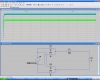
Here's what I have so far, with the addition of a properly sized bridge rectifier, I can successfully convert the AC waveform to DC. But, the waveform is not steady like I need it to be (as seen on the right of the following image)...

**broken link removed**

For DC welding, the DC current needs to be as smooth as possible, otherwise the welder has to deal with constant arc instability (thus, a crappy weld no matter how great at welding the guy making the weld is).

I have read a lot about adding a capacitor to the output to "smooth" the current to a "ripple" (shown in the next image), but due to the voltage and amperage involved, an inductor might be a better choice. Please post your opinion if you disagree.

**broken link removed**

So here's my dilemma, I can't seem to be able to find any info (that I can understand) that would help me size the inductor coil to this application.

Here's the current specs:
48-53V @ 30-225A

The voltage is almost a constant.

The amperage is selectable on the AC side of the rectifier via a knob on the front of the welder. Available max amperage can be selected from 30A to 225A. While welding at whatever amperage is selected, the actual amperage can vary depending on many factors, but not to exceed the max amperage selected via the amperage selection knob.

So that's about it.
I could use your help to finish this project.
 
Hi, and welcome to the forum. I use the same welder at home, and have no problem at all making good welds without the need for DC. The problem you face is the requirement for the capacitor is unreasonable large, due to the high currents. I do not advise you attempt to smooth the current. I know reactors are sometimes used to help stabilize the arc. See if you can find posts from the member "ImCluless" he is asking some of the same questions. Good luck.
 
Last edited:
Hi, and welcome to the forum.

Thanks :)


I use the same welder at home, and have no problem at all making good welds without the need for DC.

Me too, but the industry standard is DCEN (Direct Current Electrode Negative), not AC. So to practice what am learning in welding school, here at home, I must have DCEN.


The problem you face is the requirement for the capacitor is unreasonable large, due to the high currents.

Large, like 2 Farad kind of large. I'm aware of that. That is why I'm asking about inductor design help. (Inductor is the proper name for what you are calling a "reactor")


I do not advise you attempt to smooth the current.

To use DC, I must smooth the current. The way this is done in prebuilt units is with an inductor.

I just need help sizing the inductor coil properly.


I know reactors are sometimes used to help stabilize the arc. See if you can find posts from the member "ImCluless" he is asking some of the same questions. Good luck.

There is no "Member Search" feature on this forum (that I am aware of) which makes searching for an individual member a larger task than figuring out the proper size of an inductor coil :p

Thanks, but I still need the help I was asking for.
 
In welders the big inductor is referred to as a reactor. For a home built conversion of a AC 225 welder your best off spending th a few hundred and just buying a store ought AC/DC unit. Learning to weld good with a bad home conversion system is pointless. Once you switch to a good unit then you will need to relearn every thing again.

The cheapest conversion is to use the large diode bridge and then put the secondary windings of a large battery charger in series with one of the leads. This will give you a stable inductance to work from. Its not ideal but it works surprisingly well for a base conversion system.
 
Last edited by a moderator:
To use DC, I must smooth the current. The way this is done in prebuilt units is with an inductor.

Are you sure? It's already DC when you rectify it. Sure it has to be smooth? It's not going to be easy using an inductor. You can't just connect up an inductor and get smooth DC. Even if you could, you would have to make something custom, and the construction would be rediculous. I'm not a welder engineer. If DC welders really have smooth DC, they would probably be 3-phase, in which case you would only need to rectify the transformer output.

Your AC welder is little more than a a voltage step-down transformer. Adding a reactor or inductor to the output will only give you a phase-shifted and attenuated version of the original voltage and current shape. To smooth the current, you need something much more complex, and even then you will have significant ripple.
 
Last edited:
Ok, now I have to take back what I said earlier (forgot to consider the rectification). Look at the circuit, intended to model your welder. The addition of 10m reactor smooths the output current considerably. The current settles at about 120A, with a voltage of about 36V. The ripple current is around 5A, which is probably more than acceptable. The .3 ohm resistor models the contact resistance for the weld arc.

But you can't just connect a 10m inductor. You'll have to find a reactor that can handle the current, or build something custom. There are lots of things to consider when you build it, including the very high magnetic field, which will saturate an improperly chosen core.

I still have doubts about the practicality of the solution. And, as you might guess, this makes the arc hard to start, due to the slow rise in output voltage.
 

Attachments

  • WelderCurrent.PNG
    WelderCurrent.PNG
    70.6 KB · Views: 637
Last edited:
I really appreciate the work you have done on this.

Very interesting indeed!!
LTspiceIV.exe on what appears to be Windows Xp :)
I need to download that and mess with it some to see what I can come up with.

A ripple of as much as 10-15A would be better than a wave dropping to zero (I'm guessing) 60 times a second. Hell, I would even be willing to settle on as much as a 50% ripple if that's what It takes to realistically smooth the ripple vs. size, weight, and other design constraints.

You make a very valid point with the arc starting limitations. Getting the arc to initially start is an issue faced with even the best of stable currents. Too low of a voltage/amperage and the electrode sticks to the metal you're trying to weld (thus making the welder frantically do whatever it takes to disconnect it and start over).

One idea I've been toying with is multiple inductors and a high/low switch. I believe this is one of the ways the old school DC welding machines did it (though I'm not exactly sure how internally. Basically, a small inductor for lower amperages, and via a switch, two inductors ( series/parallel? ) for higher amperages.

Oh, all inductors will me home built unless I can find them for a very reasonable price (ie. scrap price)
 
Do you have a copy of WelderCurrent.asc that I could get from you?
I'm trying to recreate what you did with showing Amps AND Volts on the same chart, but I'm still new to LTspice.
 
Status
Not open for further replies.

Latest threads

New Articles From Microcontroller Tips

Back
Top