taranraj123
New Member
Hello,
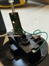
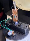
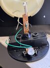
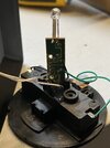
I am an electronics novice (I did some soldering in high school) and looking to get some help from the experts. I recently got a solar power led light that seems to have a loose contact from the solar cell to the PCB controlling the remainder of the circuit. The circuit does have a light sensor which is meant to turn on the LED when the light levels drop. However due to this loose contact the solar cell is essentially disconnected from the remainder of the circuit so the LED is constantly running off the battery instead. Here are some pictures of the circuit in question. I cant really tell where to solder the loose wire to on the board. Any help would be greatly appreciated!
Thanks!