Continue to Site

Welcome to our site!

Electro Tech is an online community (with over 170,000 members) who enjoy talking about and building electronic circuits, projects and gadgets. To participate you need to register. Registration is free. Click here to register now.

  • Welcome to our site! Electro Tech is an online community (with over 170,000 members) who enjoy talking about and building electronic circuits, projects and gadgets. To participate you need to register. Registration is free. Click here to register now.

Help calculating output voltage in operational amplifier using two reverse biased zener diodes

Status
Not open for further replies.
Hi! I'm a 2nd year student of EE and need help in solving this assingment.
Operational amplifier uses two reverse biased Zener diodes, calculate output voltage (in the picture 'Uiz')
 
This is how it was given in exam:
 

Attachments

  • asd.png
    asd.png
    13.2 KB · Views: 223
The principles are the same.
Using the same voltages etc. would be pointless, as that does not show you understand the basic principles involved.

Do it a stage at a time, it's nothing like as complex as the page of equations makes it out to be - though that's what you need when doing coursework..

In practice & if doing that type of calculation for one of your own projects, it's something you can pretty much just do in your head.

To give you a clue without answering it for you, the result is between -1V and -2V (note the negative voltage).
 
Do you understand the basics of how an op amp works in that configuration (?), because otherwise you are just parroting the given solution without any knowledge gained.
 
Do you understand the basics of how an op amp works in that configuration (?), because otherwise you are just parroting the given solution without any knowledge gained.
crutschow I really don't, thats why I'm asking here. Could you give a brief explanation what's going on in the configuration? And what would be the main difference between having Z1 forward biased and reverse biased in the given configuration?
As far as I can understand, input voltage is being inverted because its taken into inverted input.
Will the voltage U1 in reverse biased Z1 stay the same(0.7V) versus the forward biased Z1 and if yes why?
I dont really understand the 'left' part of configuration with zener diodes, whereas I can understand and calculate voltage gain and output voltage having Rf(R4) and Rin. Im having issues understanding how to calculate U1 and U2 voltages.
Explain to me like if I was a 5 year old.
 
Last edited:
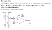
The simplest OpAmp model looks like -

1662979086530.png


Basically the output, w/o feedback, looks like simply the difference of the inputs x G,
where G is very large 100,000 into the million. If you add feedback, ground the non
inverting input you will find the output is the inverting input X ratio fdbk R to input R
minus a tiny amount due top A being finite.

The analysis for inverting here https://www.kennethkuhn.com/students/ee431/op_amp_analysis.pdf

What you find is that as the A becomes infinite the overall circuit G becomes just the ratio of
the two R's. So we have (in somewhat ideal case) an amp whose internal errors no longer
contribute to output, a simple method of amping a signal and only errors are a pair of resistors.
Again ideal case where A = infinity.

One of the outcomes of this is virtual ground, eg. the fact that if A internal = infinity then in
simple inverting case this happens

1662980524807.png


In case of non inverting virtual ground means the inverting = non inverting input
at the OpAmp - and + inputs. This makes analysis even simpler when doing calcu-
lations. Again the simple case / simple model.

Proof of this in reference above. All from simple loop and node equations.

Real models this becomes more complicated, still loop and node equations,
and AC case even more complex because the A internal to the opamp actually
does this (for many OpAmps).

1662980832038.png


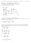
When calculating the U voltages keep in mind in ideal model no current flows
into or out of the OpAmp - and + inputs, so writing loop and node equations
simple. Becomes a simple series loop of Vin > R1 > Rf > Vout for inverting
loop.

And for the non inverting path since no current flows in or out of - and + inputs
there is no drop across R5 so U = ? Vz2 = I x R5 + U.....I = 0.....so U = ?

Again ideal model. Real OpAmps have finite input Z, finite output Z, and equations
become messy, but still loop and node. Its fun to solve for overall circuit Z, in and out,
and see what various OpAmp internal characteristics and how they affect real results.


Regards, Dana.
 
Last edited:
A zeners I-V characteristics looks like -

1662980942980.png


Vfwd looks like a diode, V ~= .7. In reverse they come in various breakdown V's.
In real zeners V-I forward characteristics are simple diode exponential behaviour.
In reverse the zener looks more like a V source, albeit with its own internal
non zero impedance. But useful to drop voltages by a fixed amount, or create
references....many applications.

Zener handbook attached.


Regards, Dana.
 

Attachments

  • HBD854-D.pdf
    374.8 KB · Views: 191
Last edited:
Yes you are correct. So now you can ignore Z1. (Assume it is open circuit.)
A very simple way of thinking about the description of an op amp is that the output will change in such away that there is zero voltage difference between the + and - inputs.
You know the voltage U2 and you can assume there is no current flowing into either input of the op amp.
So now you just have to do a few potential divider calculations.

Les.
 
The V+ input has 5.0V since no current flows thru R5. Its drop is
0 (zero).

Because of feedback that then is the voltage at V-.

The 20V zener is off, not affecting circuit.

The current thru the string of 12 V >> R1 >> R2 >> R4 >> V12
is simply that loop equation. Call this I-

Then Vout = 5.0 + I- x R4


Regards, Dana.
 
Last edited:
Status
Not open for further replies.

Latest threads

New Articles From Microcontroller Tips

Back
Top