Continue to Site

Welcome to our site!

Electro Tech is an online community (with over 170,000 members) who enjoy talking about and building electronic circuits, projects and gadgets. To participate you need to register. Registration is free. Click here to register now.

  • Welcome to our site! Electro Tech is an online community (with over 170,000 members) who enjoy talking about and building electronic circuits, projects and gadgets. To participate you need to register. Registration is free. Click here to register now.

Help a pH.D. scientist: Infrared sensor

Status
Not open for further replies.

hydrocynus

New Member
Hello.

I am an aquatic ecologist with somewhat limited knowledge in electronics.

I am trying to build a device to determine the depth of the flocculent layer in a lake. The flocculent layer is a mud layer that has a similar consistency of water. It is pretty difficult to determine its depth accurately from the surface.

I have a paper that describes a device able to measure it precisely from the surface and I think that I can build it, but there aren’t any part numbers. I need to order the right combination of parts.

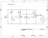
The idea is to use an infrared LED, which is placed 2-cm away from a IR photo transistor which is high when the light is blocked. The flocculent layer is sufficient to cut the beam. Once the beam is cut, the transistor is low and is connected to a 741 op-amp configured as a voltage detector, which triggers a buzzer (when the set point of the transistor is passed).
The reason infra red is used instead of a regular full light LED is that infrared is attenuated by water and thus, surface light does not interfere with the readings (at the floc layer depth, there is no ambient IR light). A 2-cm layer water does not cut the beam. A 2-cm layer of flocculent layer however cuts the beam of the IR LED.

I have attached the schematic of the design.
From the paper: "The infrared diode light source has a constant current supply (about 10 mA) determined by Rd. The amplifier is a common 741 op-amp, available at any electronics parts store.
Pin numbers for the op-amp are shown on the schematic;pins 1 and 5 are not used. The circuit board used in the assembly is a small perf-board, also available at any electronics parts store. The entire circuit operates on a 9-volt alkaline, transistor battery which should provide at least 24 h of continuous service.
**broken link removed**

Here are the parts I am thinking buying from/www.goldmine-elec-products.com
**broken link removed**

WHAT IS Rset POT 100K on the drawing? Is it a rheostat?

Thank you very much if you can help. It is quite urgent.
Hydro
 
Rset is a potentiometer. Typically you would use a small trimpot for that, such as the G13577 from Goldmine.

The buzzer you have selected requires an oscillator to drive it. You want a buzzer such as the SMB-12L Star 12VDC Buzzer from Goldmine, which operates from a DC voltage

You have selected a photodarlington transistor, whereas the schematic shows a phototransistor. A photodarlington has much higher gain and may not work properly in the circuit. You might try a G17146 from Goldmine. Or, since they are cheap, order both and see which works better.
 
they should sell a bag of various values resistors, if your only making 1 of these i dont see the need of getting 100 of each resistor when a bag of various values is maybe more useful in future?
 
How are you going to keep the lakewater off the components but alow it to flow between the LED and photodiode? The top of the diode and transistor can get wet, but the leads have to stay dry. I'm not saying it can't be done, there are many ways, I just thought it should be brought up. Good luck on your project.
 
Last edited:
Wow! You know I have been helping people on the net with flyfishing related issues, but I have to say that I did not expect so much help.

Since I need that setup to be built quickly, does radioshack carry all of the items I need? I indeed intend to use the 2nd day shipping, which kind of kill the cheap prices.

Answer to Triode:
How are you going to keep the lakewater off the components but alow it to flow between the LED and photodiode? The top of the diode and transistor can get wet, but the leads have to stay dry. I'm not saying it can't be done, there are many ways, I just thought it should be brought up. Good luck on your project.
--> Everything but the head of the LED and of the photodiode will be exposed but sealed inside a watertight casing. The author of the paper did a good job desc. the the housing of the sensor. Pretty easy to buid.
The author assume the reader would know enough about electronics for the rest... which I obviously do not.

Answer to crutschow
Rset is the potentiometer. OK. Got this now.
I do not even know what a photodarlington is... grin. Thanks for pointing me in the right direction

Answer to confounded:
I will buy a grab bag of resistors.


OK. Let continue showing my ignorance.
Rd and Rpt stand for what? They just are resistors aren't they? IT IS MENTIONED "Rd 750" on the schematics. not 750k.

For the IR LED are they all the same? I mean why the resistor and not mount it in direct? I understand that the resistor is to limit the amount of current getting to the LED. But does that mean that all the LED need the same current to function?


Now, for the soldering of the op-amp. How should I solder it? I understand that I need to read more about the use of Op-amp... but it looks like I am running out of time.
https://en.wikipedia.org/wiki/File:Generic_741_pinout_top.png

THANK YOU AGAIN.

Update: List from Radioshack. Cannot find Rd 750. Please advise.
**broken link removed**
 
Last edited:
Rd and Rpt is just the nomenclature the designer decided on. Rd for the resistor in series with the diode and Rpt for the resistor in series with the photo transistor is what I'm guessing. Rd is necessary to limit the amount of current that goes though the IR LED so it doesn't burn out. Not all IR LEDs are the same They have different illumination outputs, forward voltage drops, angular widths, etc. It's hard to say exactly which one you should use here. The one you have chosen is probably apropriate. I would imagine that you will have to do some testing and calibration of this thing once it's built. I think adjusting the 100KΩ pot will change the level of brightness (or darkness depending on how you look at it) that will turn on the buzzer. So, you should be able to adjust the potentiometer to tailor the circuit to the specific IR LED you choose. Does that sound right to everyone?

About not being able to find a 750Ω resistor at Radioshack, I wouldn't worry about that too much. Any resistor within ±100Ω of 750 will probably be good. Just keep in mind that a higher resistance will make the LED dimmer and vice versa with less resistance. Once again you should be able to adjust the 100KΩ pot to cancel out any affect that might have.

Attached below is a picture with the pin assignments of the op amp adjusted for the pin out your provided via your wikipedia link.
 

Attachments

  • OPAMP.JPG
    OPAMP.JPG
    54.5 KB · Views: 1,218
Last edited:
You will need to adjust the sensitivity pot with the unit in the dark to avoid ambient light affecting the setting.

You should use a socket for the op amp to avoid soldering directly to the leads.

How will you hear the buzzer if it's sealed in a box under water?
 
This is a neat little project! You can get rid of the op-amp by using an LED instead of the buzzer. I'll draw up a circuit for you here in a second.

You also won't have to worry about getting this wet, 9V isn't going to short in the water. Though you will want to put the IR LED and phototransistor on a separate board from the buzzer or other indicator and battery so you can lower the 'sensor board' down into the water and still see or hear the indicator.

I've actually got all the parts you'd need for it sitting around. Hit me up if you want me to make and test one for you.
 
Last edited:
They do a 680 ohm 5 resistor pack that will do you (this will give you 10ma current through infra red LED)
BTW If you want to lower or increase current and you only have 5 680 ohm resistors you can create certain resistances by combinations of parralel and series. e.g 2 in parallel gives total resistance 340 ohm therefore current 20ma etc
The socket crutschow refers to is listed as an 8 pin retention contact
Have you got a battery snap to attach your battery to board?
You havn't listed your board on your list in case you forgot
 
Hello there,


I would advise to go with a better choice of op amp or comparator.
An op amp would be LM358, or comparator LM393 or LM339.
The reason is that the voltage input range is less problematic.
If you use a comparator however you'll want a slightly different schematic.
You also may want to make sure that your IR LED and photo transistor
work at the same wavelength.
 
**broken link removed**

That way you can adjust the brightness of the IR LED. Then when the phototransistor see's the IR LED it turns on the visible LED.
 
Hello all.

I welcome any improvements of the design as long as it is kept simple. I know I am capable of soldering a DC controller kit since I have done it for another project (and you guys also helped me on that board). I do not have good technical skills, but I can solder and follow directions.

I think that being able to control the LED brightness is a plus, since this would allow me to be sure that water would not cut off the IR beam, but that the flocculent layer would.
Chudleston: Would your design allow me to see the LED in bright sunlight? I think that the buzzer is a better option... If you could test it for me, that would be nice, but I would keep the buzzer, and thus, I guess I have to use the OP-amp (another one according to MrAL) or the comparator (but with a different schematic). A loud buzzer is probably better?

MrAL:
Thanks for your suggestions. Yes, I have checked that both LED and phototransistor work well within the IR (ideally the same IR band). I am pretty knowledgeable with light, visible, but also IR and UV.

Battery connector, I have cannibalized one from a broken toy. Same for the power switch.

The LED and the phototransitor are the only ones that will be underwater. And remember only the head of both will be in contact with water. The rest is all sealed in copper tubes (two tubes running parallel and 2cm apart).

The paper say that they used telephone cord (4 wires with probably low resistance, but 4 meters long) that has 4 thin wires. The PC perf. board with the power is outside on the boat's deck.

So, I do not mind using an improved schematics and new parts from Radioshack or from a site that would deliver the parts really fast. But I need to build this over the week end so that I can properly test it on Monday on the lake on campus. D-day will be next Thursday.
Crutschow:I need to tune this up in the water. Light in the water is very much different than light outside. Water selectively absorbs certain wavelengths: Mostly red (very rapidly) and green and yellow but blue (this is why the water looks blue). This changes if you have algae in the water, chlorophyll absorbs blue and red but not green so this is why the water looks green. For IR, there is no IR that get really deep in the water. So, outside light that incl. IR will not interfere with the readings near the flocculent layer of the lake. But you are right, at first glance, I should try to tune this up in the dark (very likely at the depth I am measuring the floc layer).


I can email you the paper if needed. For copyright reasons, I cannot post it here. Just IM me.

THANKS AGAIN FOR ALL. This is awesome.

Hydro.
 
Last edited:
I think that being able to control the LED brightness is a plus,

Anytime you use a pot in this way, make sure you include a series resistor that limits current to the maximum that is allowed by the device. That way, you don't burn up the device by turning the pot too far towards minimum resistance.
 
Last edited:
Hi again,


I just noticed that your schematic shows a PNP photo detector while the device
you intend to buy is an NPN i think. You may want to double check this.
If it is an NPN, the emitter goes to ground and collector to the resistor.

Just to note, you may wish to add a small amount of hysteresis too so that
you dont have the buzzer going on and off several times for water who's
density fluctuates a tiny bit with the underwater current.

Also, the 741 isnt a good choice of op amp either because of harsher input
voltage requirements. With supplies of +/- 15v the input swing could be
only +/- 12v meaning the input always has to be at least 3v from each rail.
The LM358 (for example) can work from Vcc-1.5v right down to ground.
The input offset drift is very stable too.

BTW, Digikey has a very large selection of parts and deliver fast for cheap.
 
Last edited:
Hi again,


I just noticed that your schematic shows a PNP photo detector while the device
you intend to buy is an NPN i think. You may want to double check this.
If it is an NPN, the emitter goes to ground and collector to the resistor.

... context of schematic suggests that photo-detector is in fact NPN.
Maybe arrow on diagram of detector was drawn incorrectly.
 
... context of schematic suggests that photo-detector is in fact NPN.
Maybe arrow on diagram of detector was drawn incorrectly.

Hi again,


Ok, just as long as he is aware of this possible problem and knows the
proper wiring.
 
hi hydrocynus,
Looking at that circuit and the application, its not going to give the precise results you are expecting.:)

The design is very inefficient in battery use and is based on an obsolete OPA [741].

As the only two components you plan to have underwater are the TX/RX opto's, the circuit [ at the surface] could be improved.
For a starters, the IR emitter need not be power continously at 10mA, it could be pulsed, say at 1 to 10pps, this would permit the use of an 'ac' amplifier. etc
 
I will check digikey today. The order has to go asap now.

The IR LED has to be powered at all times. When I work on the lake, I do it on calm days. There is thus nearly no current down there.

Efficiency of the battery is not really an issue. But if there is a better design, please, provide me with a schematics and I will do this. Just try to keep it simple. Be nice. :)

Hydro

hi,
See you have a deadline to meet, perhaps next time I can talk you into a different approach.:)

I appreciate the IR in your circuit has to powered all the time, but this is my main criticism of the circuit.

I would say my design would be a little more complex, but I believe it would give you the result you require.

Please let me know how the trials of the existing design peform in the field [lake]

Regards
 
Status
Not open for further replies.

Latest threads

New Articles From Microcontroller Tips

Back
Top