Continue to Site

Welcome to our site!

Electro Tech is an online community (with over 170,000 members) who enjoy talking about and building electronic circuits, projects and gadgets. To participate you need to register. Registration is free. Click here to register now.

  • Welcome to our site! Electro Tech is an online community (with over 170,000 members) who enjoy talking about and building electronic circuits, projects and gadgets. To participate you need to register. Registration is free. Click here to register now.

Help a pH.D. scientist: Infrared sensor

Status
Not open for further replies.
Oh. I am sure that it can be really perfected. I have dead lines because, generally, you do not know whether or not you are going to get the grant, and then, once you get it, you are already late because the sponsor wants to have this done asap. When you combine this to an already busy schedule with teaching and other projects, it becomes pretty hectic.

So, I think that what I need for now is a list of parts I need to buy from radioshack or a site that ships quick for cheap.

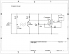
Improvements that I am willing to do are the potentiometer (with still a resistor to protect the LED) before the IR LED.

I do not know whether there is an error in the diagram regarding the arrow for the photoresistor...:confused:
If someone could redraw a correct schematic, with a list of parts, I think I can manage to have this work. I will keep you guys posted once I try it on Monday or Tuesday.

I am sampling on Thursday.
Thank you all again for your willingness to help and especially to improve it. I do not think there is much time for improvements now.

Let's call it a first prototype for now and we will improve it over time. This could give me the occasion to write another paper.

Hydro

BTW: The current design works and has generated lots of valuable precise and accurate data. So, we know it works better than anything else that was attempted before. imagine a layer of mud in clear water. The mud has a pretty clean interface because it is denser than water. As long as it is not windy, the interface is like vinegar sitting on the bottom of a beaker with oil on top.
 
Last edited:
For the original circuit, from Radio Shack:

LM741: LM741CN Operational Amplifier (8-Pin Dip) - RadioShack.com
100KΩ Resistor:100K Ohm 1/4-Watt Carbon Film Resistor (5-Pack) - RadioShack.com
100KΩ trimmer potentiometer: 100K-Ohm Horizontal-Style Trimmer - RadioShack.com
IR LED and Transistor pair: Matched Infrared Emitter and Phototransistor Detector - RadioShack.com
9V battery connector: RadioShack.com
Buzzer: 76dB Piezo Buzzer - RadioShack.com
Since a 720Ω resistor is not a Radio Shack item, putting three 220Ω resistors in series for 660Ω should be close enough:
220Ω resistor: 220 ohm 1/4W 5% Carbon Film Resistor pk/5 - RadioShack.com

ken

Interested in your project because I work with our Geology and Biology Departments, building their field toys....I mean scientific instruments. ;)
 
Last edited:
I am done, but it does not work

Hello all.
I got the parts from radioshack. Thanks.

I followed scrupulously the schematic. The only change I have made is that I used a trimmer potentiometer (1 kilo ohm) for the IR LED. That allows me to change the IR intensity. Everything else remains unchanged.

What I have is that the buzzer emits a buzz at all times.
The IR LED works (my camcorder says so).
When the IR LED is in front of the phototransistor, the resistance is very high. When the IR is away from the phototransistor, the resistance is low.

So, did I buy a PNP or a NPN phototransistor? It looks like this might be my problem?

Also, for the 100k potentiometer. I soldered the two legs of it that give a constant resistance of 100k. The third leg (variable resistance) is connected to the "inverting input" of the op-amp.

Can someone tell me in which configuration the Op-amp is? voltage follower, integrator etc.
I indeed do not get what it does.

Thank you very much.
Hydro.


UPDATE: I read again what you guys wrote about the phototransistor and I changed the wiring of the phototransistor (long leg to ground and short leg to positive). Now, it works.
The only thing that remains is that the buzzer emits a slight buzz, very small, yet audible and potentially horrendous when the phototransistor is lit by the IR LED. When the LED is away, the buzzer emits a loud sound.
Any idea?
 
Last edited:
I wouldn't recommend using the LF351 because it's an old JugFET op-amp which will more than likely suffer from phase inversion and therefore be unsuitable for use as a comparator.

I would recommend using an LM311 comparator with a few modifications to the origional schematic.

The buzzer is now connected from the output to +V as the LM311 can only sink current; the + and - inputs have been exchanged because of this. A 1M resistor has been added to add some hysteresis which will make it more stable.
 

Attachments

  • IR barrier.PNG
    IR barrier.PNG
    62.9 KB · Views: 264
I think I may have errored in the Radio Shack photo transistor. It doesn't say in their "technical" page (imagine that ;) ), but I'm sure it's an NPN. I had one of my students use them in a laser harp demo project. Almost exactly what you are doing.

If you use your original circuit diagram, and flip the photo transistor so the emitter goes to ground (-9V) and the collector goes to Rpt, it should work. I think Peter Meyer drew it wrong and my brain was else where.

Sorry.

Ken
 
Last edited:
I did think that was odd, I've never seen a PNP phototransisor before.

If it's a PNP then the schematic is right, if it's an NPN the emitter and collector connections should be reversed.
 

Attachments

  • IR barrier.PNG
    IR barrier.PNG
    62.5 KB · Views: 344
No problem to have not caught this.

I guess that for my upcoming field work, he design I have will work. I can also remove the buzzer if it bothers too much and look at the voltage output.. or event look at the phototransistor resistance. I am indeed running out of time now.

I will however order the parts for the lm311 comparator design. THANKS!
However there are many LM311 : LM311N, LM31M, LM311DP, LM311P. Which one should I pick?

Thank you again for your tremendous help.

Hydro
 
They're basically the same part apart from the LM31M which is probably a typo, you probably mean LM311M which is a military specification device.

The differences are temperature range, case style and some might have a slightly better specification than others. Choose a through hole device with the desired temperature range.
 
If you have any resistors laying around try putting them in series with the buzzer to lower the volume. Or a pot if you have an extra one so you can adjust it.
 
Thanks for the clarifications.

Question 1:
To prevent the buzzer from buzzing at about 1.5-3 v, can I use a resistor that would be infinite when the voltage is under 5V and then would be zero when the voltage is above? I was thinking about a Zener diode?
Would this one work for me then?
1N4733A 1W Zener Diode - RadioShack.com

Also, I tested the flocculent sediment sensor tonight.
The first surprise was that the buzzer went off when the sensor touches the water. Water attenuates IR very fast, but I did not expect it with an IR LED placed at 2 cm away from the phototransistor.

I tweaked the trimpot of the IR LED and increased the IR until the buzzer stopped buzzing.
When I touched the flocculent sediment, the buzzer went off. So, it works in the lake on campus... but the lake I shall survey next Thursday has murky water. So I guess more tweaking will be needed.
To the worst, I maybe will have to move the sensors closer and this demands some substantial work. I hope that when the IR diode is maxed out (See question 2 below), the murky water will not cut the IR beam off.

In the future, I will have two potentiometers that I can tweak without opening the box where the electronics is. It looks like there will always be a need for some tweaking.


Question 2:
Last question, what would be the minimal resistance I should put to protect the IR LED? Right now, it is directly connected to the trimpot... and as you know, these guys are very sensitive (1 turn does it all).


THANKS AGAIN SO MUCH!
Hydro.


chuddleston: I tried this, but what happens is that that, when I do not hear the buzzer, when it goes off, it emits a very low sound (kinda the same sound intensity as my background buzzer before I tried to lower it).
 
Last edited:
ex-hydro.
BTW: The current design works and has generated lots of valuable BTW: The current design works and has generated lots of valuable precise and accurate data. So, we know it works better than anything else that was attempted before. imagine a layer of mud in clear water. The mud has a pretty clean interface because it is denser than water. As long as it is not windy, the interface is like vinegar sitting on the bottom of a beaker with oil on top.. So, we know it works better than anything else that was attempted before. imagine a layer of mud in clear water. The mud has a pretty clean interface because it is denser than water. As long as it is not windy, the interface is like vinegar sitting on the bottom of a beaker with oil on top.

hi,
Sorry to hear that the circuit is not performing as expected.

I can only repeat my earlier post, this design will not IMHO give the valuable precise and accurate data that has been claimed.

Can you say who used this circuit to capture the claimed data.?
 
Last edited:
ericgibbs:
Here is the paper
Myers, P., and C.L. Schelske. 2000. An inexpensive, optical (infrared) detector to locate the sediment/water interface in lakes with unconsolidated sediments. J Paleolimnol 23:201–205.
That paper got fairly cited.

Now, if you guys think that the design is no good, we can work together on a better design and publish the work. I think that this sensor is still pretty good if you compare to whatever was available before.

If you want the paper IM me with an email address and I shall send it to you as an attachment.

Hydro.
 
To prevent the buzzer from buzzing at about 1.5-3 v, can I use a resistor that would be infinite when the voltage is under 5V and then would be zero when the voltage is above?
What do you mean?

Assuming you're using the LM311 there shouldn't be any voltage across the buzzer when it's off, the 1M resistor shouldn't pass enough current to power it. If it's a problem, put a 100k resistor in parallel with the buzzer.

The first surprise was that the buzzer went off when the sensor touches the water.
Were the electrical connections to the back of the sensor fully water proofed?

If not, water could have asilly got in and short circuited the sensor making the circuit think that it was illuminated.
 
Hello Hero99:

- Well, I have a voltage going through the buzzer when the phototransistor has quite low resistance. I am pretty sure the wiring is right. I keep the suggestion of having a resistance in parallel. I am not currently using the LM311 but the LM741.

- The water attenuates IR pretty quickly. All the wires are embedded in caulk. There is no way water can make its way pass the tips of the LED and phototransistor which are the only components in contact with water.

Hydro.
 
Last edited:
ericgibbs:
Here is the paper
Myers, P., and C.L. Schelske. 2000. An inexpensive, optical (infrared) detector to locate the sediment/water interface in lakes with unconsolidated sediments. J Paleolimnol 23:201–205.
That paper got fairly cited.

Now, if you guys think that the design is no good, we can work together on a better design and publish the work. I think that this sensor is still pretty good if you compare to whatever was available before.

If you want the paper IM me with an email address and I shall send it to you as an attachment.

Hydro.


Hi again Hydro,

I had worked on a device similar to what you are talking about here
about two or three months ago. It did not have to work under water,
but the distance between IR LED and Photo transistor could vary a little
bit (and an additional requirement was a pass code had to be entered
to get the device to work). What i found was that it was best to
incorporate an auto calibrate mode of operation that eliminated having
to constantly tweek pots and try to get things right like that or have
to adjust the distance or other things.
An auto calibrate mode however can really only be incorporated in
a design that includes a micro controller, however the inclusion of
such makes life a whole lot easier.
Im not sure if you would want to go with a micro controller or not,
but i thought i would mention it because then you can calibrate
for any environmental situation by simply pressing a 'calibrate'
button and moving the sensor first to the water level you want to
detect as 'clear', and then maybe a few seconds later to the level
you want to detect as the 'flocculent' level. The box would then
be calibrated.
Other features such as auto adjust IR level and the like can also
be incorporated for environmental situations that vary considerably.
I think this would make a really nice instrument if you dont mind a
bit more complexity.
Another possibility would be two sensors where the device looks
for a certain differential density and acts on that to calibrate.
That would mean moving the box to the level to detect and pressing
"calibrate".
Im sure other members here could elaborate more on ideas like this too
if you are interested in creating a really nice piece of equipment.
Cost isnt very high either... two dollars US for a micro controller for
example.

One question we should have asked a long time ago too:
What kind of resolution do you need for this device...that is, do you have to
be accurate to within one foot, one meter, one inch, one cm, one mm, etc. ?
 
Last edited:
Hello Hero99:

- Well, I have a voltage going through the buzzer when the phototransistor has quite low resistance. I am pretty sure the wiring is right. I keep the suggestion of having a resistance in parallel. I am not currently using the LM311 but the LM741.
Hydro.

hi hydro,
The 741 opa as mentioned is a very old device and has a poor specification.
One of its short comings is its limited output voltage swing, its not from 0V thru Vbatt, but more like +1.2V thru Vbatt -2V.

That +1.2V maybe just enough to keep the buzzer sounding, you could try adding a small diode in series with the output of the LM741 and the buzzer, that would drop the 1.2V down to about 0.4ish.

Diode Anode to the LM741 and Cathode to the buzzer.

OK.:)
 
Hi Eric,

I had suggested an LM393 or LM339 or even a LM358 long time ago, but
he seemed to not understand the significance of this kind of suggestion.

More recently i suggested a uC because that would make one heck of an
instrument, provided of course the slightly higher complexity is acceptable.
Of course the added complexity only comes in the form of an algorithm, so
maybe that's not really more complexity anyway.

hi Al,
I would agree that some form of calibration is required else he will be forever chasing his tail, tweaking the pots to get a reading and never have a true datum reference.

It would be an ideal project for an mcu.
 
Status
Not open for further replies.

Latest threads

New Articles From Microcontroller Tips

Back
Top