Continue to Site

Welcome to our site!

Electro Tech is an online community (with over 170,000 members) who enjoy talking about and building electronic circuits, projects and gadgets. To participate you need to register. Registration is free. Click here to register now.

  • Welcome to our site! Electro Tech is an online community (with over 170,000 members) who enjoy talking about and building electronic circuits, projects and gadgets. To participate you need to register. Registration is free. Click here to register now.

HELP: 7812 circuit problem

Status
Not open for further replies.

gnuga

New Member
Hai,

I've been trying to build a power supply from 7812. For safety I used a transistor TIP42 to accomodate the extra current. However, the 7812 & TIP gets to hot even with a heatsink.

The load is two stepper motor from old hard drive (which I do not know the current needs, is there any datasheet for these? it's just a stepper from old 5 1/4" hard disc), and two computer fans rated @0.19A.

The datasheet of TIP 42 says it can handle continous current of up to 6A. Those loads I think is less than 2A total, right?
Why does it gets hot? Espescially the 7812 side.

I use a 3ohm 2W resistor between the Emitter & Base of the TIP42 as describe on the datasheet. I do not how to count the R. The two equations are different one and the other.

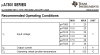
Here's the pic from the 7812 datasheet:
**broken link removed**
 
You don't mention the input voltage, or what the actual current output is - so iy's not really possible to make suggestions. Apart from the obvious one about the size of your heatsinks.
 
Hai,


Why does it gets hot?
Power dissipation. Post the values of VIN, VOUT, and ILOAD and I can show you how to calculate the power.

It may also be oscillating. If it is, increase the amount of capacitance on the input and output.
 
Last edited:
The configuration is wrong. You have the TIP and 7812 in parallel. You're biasing the transistor on HARD, and the poor regulator is trying to handle a near-dead short back to the supply. The usual configuration is to have the OUTPUT of the regulator drive the transistor's base to bias the transistor to the output voltage you want. Basically, just move the TIP's base from the regulator's input to it's output. This makes for a pass-transistor power circuit. You'll need a bias resistor between the output and the base. This is largely a matter of finding the transistor's gain, then the amount of current you are using for the load. Let's say the gain is 100 and the load current is 5 Amps. This means the TIP's base current will need to be 5/100, or 50 mA, to get 5A out. This makes the base resistor 12V/50mA, which is 240 Ohms. The power dissipated in the resistor is I*I*R, or 0.05 * 0.05 * 240, or 0.6 Watts. Plan on using a 1 Watt resistor for the base resistor! And lotsa heat sinking for the transistor!

Now, as for the drive motor loads, if your talking the motors that turned the drive's platters, plan on at least 3 Amps each on power up, and considerably less at full speed, IF you're turning something as massive as a hard drive's platter set. In the end, only inserting an ammeter in line between the supply and the motors will actually tell you what's happening. What would be better is to insert a 1 Ohm power resistor in the current path and applying an oscilloscope or data logger across the resistor to measure the initial draw at power up. This eliminates the DMM's slow sampling rate missing the peak current at the moment you apply power.

Umm, that's the best I can do. Good luck with your project.
 
The configuration is wrong.
No.
It is correct, you are wrong.
The transistor is turned on when the regulator draws about 267mA.
The transistor is the current-booster that is shown in the datasheets.
 
It is correct.
That is the way we always connected them, I put many such circuits on data sheets. One thing: when you add the PNP, it increases current gain around the regulator which changes the effective gain of the control loop. I usually throw a big honking cap on the output to keep it stable (like 470uF). Not sure if it is mandatory here, but those 0.1uF ceramics love to resonate and I would parallel them with larger electrolytics just to be safe.

The other warnings: the external PNP has neither current limiting protection or thermal overtemp protection as the IC does, so these types of designs must have good heatsinks and be careful not to short the output or they will blow up.
 
Last edited:
Here's my actual design:

**broken link removed**

As you can see, I'm just copying the datasheet with additional C input of 6800uF. The 20V input is the transformer secondary side. Oh My GOd, I haven't measure the VDC from the capacitor.

Let's assume it must be less than 20 V right? so still safe.
Can anybody help with the equation?
If I want I output max 3 A and Vo of 12volt, and only 0.1 A goes through the 7812, the rest through the TIP 42 (hfe between 15 to 75).
Those two equations yield different results??
 
Let's assume it must be less than 20 V right? so still safe.

Assuming the transformer is 20V, then the voltage to the regulator will be about 30V - so 18V dropped across the regulators at 3A, that's 54W of heat to dissipate. So massive heatsinks, and a TIP42 is probably far too small.
 
Nigel:
OMG, than my 7805 is done for sure :(
I think I should change the transformer right away!!
RUN!!!
 
Last edited:
hi,
The 20Vrms will give Vpeak = 20 * 1.414 =~28V, less 2 diode drops.
 
The max input for a uA7805 is 30V but a max of 25V is recommended by Texas Instruments.
It reduces its max output current when it has more than 20V input.
 
Bridge Rectifier?

Following your suggestion, I've change the schematic into the following:
(basically I only change the resistor value to a bigger one to reduce the current flowing to the regulator & changing the output capacitor & also reduce the input voltage).

**broken link removed**

The first two schematic above is working wonderfully as they only draw small current ( only for AVR for the 7805 & stepper motor for the 7812).
However the last schematic to drive a Halogen Lamp of 6V/15W, the MJ 2955 transistor gets so hot & ,surprisingly, the bridge rectifier is done. I've never experience a blown up Bridge before :(.

The bridge was 5 Amps Bridge and now I replace it with a 10 Amps one. However this one gets to hot too. I'm afraid it's already gone too. Do you know how to check whether bridge is still ok or not?

I connected both the (~) pin to the transformer's (not a CT one) pin of 12 V and 0V. The (+) pin to the (+) pin of C input. The (-) goes to the (-) of the C input which is also the ground side. Is that correct?

My friend said that the (-) bridge pin shouldn't be connected to the ground. Instead, he said used the transformer 0V for the ground.

Which one is correct? :confused:
 
This is from the latest datasheet for Texas Instruments uA7800 series regulators:
 

Attachments

  • uA7800 series.PNG
    uA7800 series.PNG
    13.5 KB · Views: 665
Can somebody explain about the bridge rectifier phenomena?


I found after limiting the regulator current to a 100mA (to be very safe), the regulator is in peace (cool & steady), and yes, the transistor now has an additional burden due to the increasing of collector current.
 
Status
Not open for further replies.

Latest threads

New Articles From Microcontroller Tips

Back
Top