Electro Tech is an online community (with over 170,000 members) who enjoy talking about and building electronic circuits, projects and gadgets. To participate you need to register. Registration is free. Click here to register now.
Welcome to our site! Electro Tech is an online community (with over 170,000 members) who enjoy talking about and building electronic circuits, projects and gadgets. To participate you need to register. Registration is free. Click here to register now.
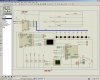
I don't use Proteus or breadboards (unreliable), I'd prefer to hand wire prototypes as I'm from the age of wire-wrapping. I do use the debugger and MPLAB simulator.
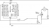
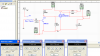
Hey I inserted resistance instead motor and everything worked fine! I think it's really EMF but flyback diode didn't help I inserted it as shown on figure..... why didn't it work? unfortunatelly I don't have oscilloscope to explore it
Hey I inserted resistance instead motor and everything worked fine! I think it's really EMF but flyback diode didn't help I inserted it as shown on figure..... why didn't it work? unfortunatelly I don't have oscilloscope to explore it
Metal–oxide–semiconductor field-effect transistor are voltage controlled. zhaniko93 is using one that's not able to turn on at 5 volts right. His 9 volts motor supply make's it a if'e it may work some time and may not. In Mulisims 11 it will not turn on with 5 volts at the gate.
Hi,
The decoupling you show on that diagram is far too little for reliable operation when driving loads.
Use at least a 47uF or 100uF and two or three 100nF, one located near the PIC
This site uses cookies to help personalise content, tailor your experience and to keep you logged in if you register.
By continuing to use this site, you are consenting to our use of cookies.

 I inserted it as shown on figure..... why didn't it work? unfortunatelly I don't have oscilloscope to explore it