Andy1845c
Active Member
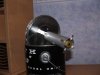
I received this as a Christmas gift from my dad. I have been wanting to get into ham radio for a while, and am working on getting a rig set up.The last thing I need is another iron in the fire, but oh well")
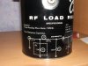
I am confused on what the 50hm: resistor should read with an ohm meter. I know, that sounds stupid, but it reads 77.1hm: on mine. I checked some new resistors with the meter, and it seems okay, so I suspect the 50hm: resistor could be bad. I googled this problem and came up with mixed information. Someone said the resistor could have been overheated and be ruined, some say these can't be hurt. Some say that running them in the wrong type of oil can make them read high. Can anyone tell me what is correct?
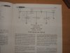
I am struggling to understand impedance. The can reads 50hm: impedance. That dosn't simply come from the 50hm: resistor, does it?
Are there any ham radio gurus out there that can lend some advice on this. Will it be any good to tune my radio the way it is?
I am confused on what the 50
hm: resistor should read with an ohm meter. I know, that sounds stupid, but it reads 77.1hm: on mine. I checked some new resistors with the meter, and it seems okay, so I suspect the 50hm: resistor could be bad. I googled this problem and came up with mixed information. Someone said the resistor could have been overheated and be ruined, some say these can't be hurt. Some say that running them in the wrong type of oil can make them read high. Can anyone tell me what is correct? I am struggling to understand impedance. The can reads 50
hm: impedance. That dosn't simply come from the 50hm: resistor, does it? Are there any ham radio gurus out there that can lend some advice on this. Will it be any good to tune my radio the way it is?