imane tech
New Member
Hello community!
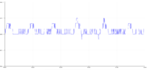
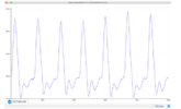
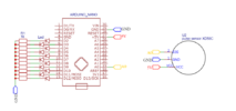
I'm new on this forum. I'm working on my heartbeat sensor (pulse sensor) that uses PPG technology, i've got some troubles to calibrate the sensor. Actually, i don't know how to choose a "threshold value" in order to have the shape of that ppg signal when i put my finger on it. Do you have any idea, please ? If you want me to give more details, feel free to ask me, and thank you!!
I'm new on this forum. I'm working on my heartbeat sensor (pulse sensor) that uses PPG technology, i've got some troubles to calibrate the sensor. Actually, i don't know how to choose a "threshold value" in order to have the shape of that ppg signal when i put my finger on it. Do you have any idea, please ? If you want me to give more details, feel free to ask me, and thank you!!