Electro Tech is an online community (with over 170,000 members) who enjoy talking about and building electronic circuits, projects and gadgets. To participate you need to register. Registration is free. Click here to register now.
Welcome to our site! Electro Tech is an online community (with over 170,000 members) who enjoy talking about and building electronic circuits, projects and gadgets. To participate you need to register. Registration is free. Click here to register now.
Not at all, the config bits should be set in your source code, the PICKIT3 software (as with all properly written software) reads the config settings from the HEX file.
I suspect you're simply ignoring the config bits, which could be the reason for you problems.
I can't figure out the method used to do it, with all the little boxes that don't say MCLRE on or BODEN off.
After looking at the datasheet for the 628A it is as clear as mud to me. They seem to be trying to confound people even to the degree of saying that a "1" in some address bits means its off and would mean its on in another.
Baffled again I'm affraid. Al
Edit. I almost forgot to say that when I got a 628 to build and flash correctly the program actually worked flawlessly. Now I have another 3 628As that I can't use until I can recreate the thing I accidentally did with the one that is now OK.
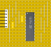
I've attached veroboard layouts for a simple programmer adaptor for the PICKit2/3 - build it, and try reprogramming the 628a's using that rather than ICSP.
I should have said, I'm using a board I got from ebay that has 3 ZIF sockets on it, designed for the Pickit.
Though I have had some success with it already, there are six jumpers on it that it says to close all for PICs and remove all for other devices. Other than that information there are no instructions for the board, but as I said I have had success once I can only assume that the jumpers are ok.
I will still build your board if you think it neccessary. Is there any advice on how NOT to make unusable 628s?
Also as to the config bits, I have always used the settings in the Picflash to set them as when I read the datasheets for Pics and look at the usages of the config bits in picbasic or mikrobasic there are always conflicting ways of doing it, MCLR or MCLRE etc. Is there a convention for the config syntax that is accepted generally and where do I find it if there is? Datasheets or Basic user manual instructions?
If you do and you read the manual for the program jumpers, you will see that they don't go into any detail about them. I would be very happy if someone could explain what they actually do rather than just RB3 as PGM etc.
You can blank the 16f628a with the pickit3 I've fixed some of them that set configure wrong. There are setting in the stand alone software that force the chip into program mode. Post a link to the ZIF socket adapter.
If you force MCLR at start and set to lowest programming speed fixes most any chip.
Your using MPLAB you cant set configures with the stand alone software.
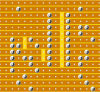
The Pickit3 software will let you set the configure bits. Let me clarify this you can change a bit value but its not a list like mplab uses and easy to set the wrong thing that way View attachment 63800
Mplab will let you set any thing you like by a list and even not set the config at all when programming the chip
Try the force pickit3 and set for a 16f628a and blank the chip and start over. With a blank chip
What do you mean "force"? Is it something to do with the config bits? I noticed the shot you posted showed all 1s. From what I have worked out mine should read(--1---101110000) The last 5 bits being for Int Osc No Clock out.
Or is there a setting somewhere that says "force"?
Sorry to keep asking but I just cannot get past this and re-animate my dead Pics.
There a setting that manually sets the the pickit3 to force programming the chip. It sets the chips voltage for programming so that on power up its ready to program it doesn't get to run code. But starts program mode up. That should let you erase the chip and load new code the configure window I posted is not for a 16f628a. Just to show the window not the best way to set bits
If you do and you read the manual for the program jumpers, you will see that they don't go into any detail about them. I would be very happy if someone could explain what they actually do rather than just RB3 as PGM etc.
HI Al I have an EasyPIC 4 and other EasyXXX boards, they describe the program jumpers near the start of the manual.
There is only two positions the jumpers go in, and you cnage between the two jumper "patterns" depending on which PIC you are using.
If you had the jumpers wrong no 628s would have programmed.
I'm pretty sure you have an issue with the 16F628A and the LVP pin (I think it's PORTB.F3?) as i have had similar issues on mine.
The fix is very easy. makse sure nothing is connected to PORTB (ie no other external boards are plugged into your EasyPIC5) then set the PORTB pullup jumper to PULL DOWN. That is important, it holds the PIC LVP pin LOW during the bulk erase and programming cycles.
That's all you have to do to get the other PICs working, and of course to make sure "LVP" is DISABLED in the programmer menu and in your project settings (the CONFIGs used by your project).
Thats sorted the programming mate, faulty ones now will take programs ok.
But only one of the four 628s I have will actually take my proper program!
Now I can program them I have discovered that the other 3 will only work in part ways.
None of them will work with the LCD part of my program which is all on port B, whereas if I write a simple LED test program then some of the LEDs on port B will behave as expected but not all!
It seems that the Pics all have certain powers like superheroes do and the Lex Luthor to them all is LCDs.
Anyway I have ordered some more 628s and will post a follow up when they arrive.
Been investigating further and discovered something strange.
Since Roman's post about pulling RB4 down while programming I have been able to program some of the 628As but not correctly enough to work with my LCD. So I thought since the problem I was having programming was caused by PORTB.4 and the RS Bit for the LCD was on that pin I would change the RS Bit to a different pin.
I made the RS bit PORTB.6 and tried again - same result Doh!
Finally I decided to move the E Bit from PORTB.5 to PORTB.7 and try it again - success!
So far I have only tried this with one of the 3 PICs that wouldn't work with the original program, but I will continue investigating as it bugs me when I hit a wall with something. Has anyone else had problems with specific Pins not working correctly on PICs? I seem to remember my mate Eric Gibbs saying he has, at least I think it was Eric.
Anyway, back to testing and I will post any further developements in the saga.
It might be possible that you have physically damaged the FET output drivers in the port pin. It's rare but if it had a sustained short circuit on that pin while you were driving it as an output it can fry the FET drivers.
You are using a good test procedure, if you swap in the PIC (I assume they are socketed?) and one lights the LEDs but the other doesn't it looks like the pin is fried.
Just check all the project config settings etc in the edit project menu, and then use the "build and progam" icon on the right of the MikroC screen, so it will use the PROJECT config settings.
If you are loading the programmer manually there is a chance you are programming the PICs with the same hex code but with DIFFERENT config settings.
It's always a good idea to visually check the config tickboxes in the programmer to make sure they match anyway, before you hit the program button.
I've found that 2 PIC pins fighting each other generally doesn't blow up the pins as each has maybe 60+ ohms internal resistance so that's 5v over total 120 ohms so the current is limited to <50mA or so, not likely to fry the pin FETs straight away. If it was a long period like that it could have fried the pin but I can't remeber every frying a pin that way.
The few times I have fried a pin was from accidentally applying 5v or GND to an output pin which is maybe 120mA, but even then they usually survive if it's only a few seconds. The last time I remember a PORTA pin got connected to a 12v 1.5A supply, that fried the pin even though it was an input at the time.
If a PIC in a new project doesn't seem to be working right away, I power down and carefully go through the code and check all the hardware including for shorts and pin assignments etc. That way it's not powered up for extended time in a short condition.
On my main workbench i have a 5v supply with selectable current limiting so I select 20mA, 50mA etc and it can never fry the PIC, actually it's a good indicator of a short as the current limit LED comes on so it's instantly visible as a fault!
Bigal, it's a little embarrasing my favorite supply for that work is one I whipped up in a hurry then got so much use I put it in a more presentable box.
It is simplicity itself, it runs from about 14v DC and uses a 7805 regulator to make the 5v, then before that there is a LM317 and 1 resistor to set the current limit. Actually when I prettied it up i added a centre-off toggle switch to change resistors so the toggle switch selects 20mA, 50mA and 100mA.
So that's 2 simple regulators and a couple of resistors and a switch!
If you need to add a current overload LED, the LM317 drops less than 3v normally, but >3v when current limiting. So you can just use a LED in series with a few cheap diodes and a resistor and the LED will only light up when the LM317 goes into current limiting.
I'll snap a photo of the front of the supply if you like.
Well the bench PSU I have is an old RS 489-100 that has a variable -15 0 +15 and a static 5v. I already modified it by adding a voltmeter with 7 segment display - switchable to either - or + reading.
There is plenty of room inside the box and also places still to put another display or LEDs and switches. I have some rotary switches up to 12 ways which may be ideal for the job of switching the current ranges.
Roman, I would like to see a photo of your PSU, its always good to see other peoples work, it gives others ideas and helps decide how to build things.
I also have another problem. Even though I have eventually sorted most of the proiblems with my current circuit, I decided to add a piezo sounder to the mix and it works fine on the EasyPic5 board, using sound out on RB4 and Gnd, but on my circuit board with the same connections the piezo just clicks and this is with the same Pic chip!
I then put the Pic back in the EP5 and it worked ok again. Then I removed the piezos connection to the PortB4 header pin and touched it to the actual Pic pin and it just clicks like on my circuit!
What can be the difference between the actual pin and the header pin? I am using no pull ups or downs on the port the only other connections to PortB are the LCD data, Rs and E pins.
Any ideas?
PS I have measured the continuity between the connections on my EP5 and my circuit connections and there is no difference I can find (Pic removed).
This site uses cookies to help personalise content, tailor your experience and to keep you logged in if you register.
By continuing to use this site, you are consenting to our use of cookies.