Continue to Site

Welcome to our site!

Electro Tech is an online community (with over 170,000 members) who enjoy talking about and building electronic circuits, projects and gadgets. To participate you need to register. Registration is free. Click here to register now.

  • Welcome to our site! Electro Tech is an online community (with over 170,000 members) who enjoy talking about and building electronic circuits, projects and gadgets. To participate you need to register. Registration is free. Click here to register now.

Hardware ESC 8xSERVO CONTROL on PIC (Oshonsoft BASIC)

Status
Not open for further replies.
From that table of values, it's doing the 'i*250' portion as a byte (with a byte result) and then adding that to 2000.

I don't know what the syntax would be to get it to do the math using words... never used it.
Tumbleweed worked it out earlier. (#505)
It turns out that making i a word fixes it.

Will be interesting to see what happens with interrupts again.

Mike.
 
Here's a version that (hopefully) should work on interrupts,
Code:
Define CONFIG1L = 0x00
Define CONFIG1H = 0x06 '8mHz XTL x4 =32mHz
Define CONFIG2L = 0x0c
Define CONFIG2H = 0x20
Define CONFIG3L = 0x04
Define CONFIG3H = 0x80
Define CONFIG4L = 0x80 'Set for HVP
Define CONFIG4H = 0x00
Define CONFIG5L = 0x0f
Define CONFIG5H = 0xc0
Define CONFIG6L = 0x0f
Define CONFIG6H = 0xe0
Define CONFIG7L = 0x0f
Define CONFIG7H = 0x40

Define CLOCK_FREQUENCY = 32
Define SINGLE_DECIMAL_PLACES = 2
Define STRING_MAX_LENGTH = 20

Define SIMULATION_WAITMS_VALUE = 1 'Comment in for SIM out for PIC

Dim wordTemp As word
Dim ServoCount As Byte
Dim i As Word
Dim ServoPos(8) As word
Dim frame as Word

OSCCON = %01110000  '& h70
TRISA = %11000000   '7=OSC, 6=OSC,
TRISC = %11111010   '6=1-slave4431_cs, 2=74HC164 CLK, 0=74HC164 DATA
LATC.0=0            'ensure data is low
LATC.2=0            'and clock
For i = 0 to 7
  LATC.2=1                 'send positive clock edge
  servoPos(i)=i*250+2000   '1ms(2000) to 1.875(1 7/8ths - 3750)ms in 1/8th mS steps
  LATC.2=0                 'send negative edge
Next i
TRISC=%11111010           'CCP0 (RC2) & RC0 output
servoCount=8              'cause it to reset
T1CON=%00100000           'prescaler = 4
T1CON.0=1                 'start timer
CCP1CON=%1000             'will go high on interrupt - will start a 0.5mS pulse
frame=1000                'start everything in 4000 cycles
PIE1.CCP1IE=1
INTCON.PEIE=1
INTCON.GIE=1
While 1
  'adjust servo positions here
wend

end

on high interrupt   'go via location 0x0008
save system
  If PIR1.CCP1IF Then         'has CCP1 triggered?
    wordTemp.HB = CCPR1H      'get value of CCPR1 into wordTemp
    wordTemp.LB = CCPR1L
    If CCP1CON = 0x08 Then    'have we started the 1000 cycle pulse
      CCP1CON = 0x09          'yes so end the pulse after 0.5mS
      wordTemp=wordTemp+1000  'adding 1000 will make pulse 0.5mS long
    Else
      LATC.0=0                'clear the data pin
      CCP1CON = 0x08          'No so output the timed gap
      if servoCount<8 then
        'still doing the servos so add remainder of time
        wordTemp = wordTemp+servoPos(servoCount)
        wordTemp=wordTemp-1000'knock of the 1000 (0.5mS) already elapsed
        frame=frame-servoPos(servoCount)
        servoCount = servoCount+1
      Else
        'done all the servos so just the frame gap to do
        wordTemp=wordTemp+frame
        frame=39000           '40,000(20mS) minus time of positive pulse(0.5mS)
        servoCount=0          'start all over again
        LATC.0=1              'will become first pulse
      Endif
    Endif
    CCPR1H = wordTemp.HB      'put value back into CCPR1
    CCPR1L = wordTemp.LB
    PIR1.CCP1IF = 0           'clear interrupt flag
  Endif
resume
resume

There's no priority set as the default is to vector to the high priority interrupt (0x0008).

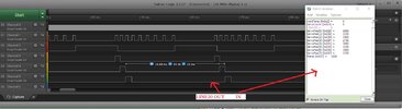
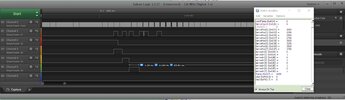
Can we just try this as is and see if it works?

Here's a picture of the ISR in Notepad++,
View attachment 140498
I hope you agree that having the indenting aids in following what the code is doing.
The dotted lines match up the If, Else & EndIf that go together.
The first If isn't actually needed as CCP1 is the only thing that can trigger interrupts but that's about to change.
The second If decides if we're doing the 0.5mS positive pulse or the remainder of the servo time.
The third If decides if we've done all servos and if so outputs the remaining time (in frame) and resets everything.

Also attached is the text file.

Mike.
Hi M,
Working!

Yes, I agree, but Osh removes the indents, when I save the file.
I'm not sure if there's a way of doing it cleanly, I'll try different methods.
I just re-indent it each time, and sometimes get it wrong.
C
 

Attachments

  • #518.jpg
    #518.jpg
    165.3 KB · Views: 156
Last edited:
Strange, it seems in some cases, versions of the Basic "compiler" may produce integer values when multiplying byte "i" by 250. However, in the PIC18 IDE (not compiler version), I get the proper values calculated:

Code:
Dim i As Byte
Dim servopos(8) As Word

For i = 0 To 7
    servopos(i) = i * 250 + 2000
Next i

End
Produces the right values:

View attachment 140500

Is it possible that somehow servopos is being modified elsewhere?
Also, integer overflow could produce values that change by 6, based on multiplying by 250, but a byte can only hold 255 maximum.
Put a "Break" after the Next i statement and verify the values are correct before allowing the rest of the code to run...
Hi S,
Who is this addressed to?
C
 
OK, that's good. Do you have a GPS attached to this chip? If so, is it attached to the RX pin?

What else does this chip need to do?

Mike.
Hi M,
Yes, there is a GPS connected to the RX, I can't post the GPS PARSE, yet, as it is being tidied up by my mate ((Procedures etc). There is a GPS on PIC1, that he's working on, which should work on this PIC4.

If you add a 'MAIN: goto MAIN' LOOP I can try some tests.

It's difficult to remember all that this PIC will be doing, as I haven't given it much thought, till all of the peripharals are working throughout all 4xPICs. It's complicated!

The 4431 will PARSE the GPS read the SPI DATA from PIC one, and calculate stuff like forward, reverse, tilt, steering angle etc.

EDIT: Before anything I would like to be able to connect 8xSERVOS, and get them all to move as directed.
C
 
Last edited:
If you add a 'MAIN: goto MAIN' LOOP I can try some tests.
Just add your code to the while wend loop that is currently empty.
EDIT: Before anything I would like to be able to connect 8xSERVOS, and get them all to move as directed.
Just try it, it should work as is.

I think adding reading of the USART in the ISR is the way to go. Then the main loop (while - wend) can do the parsing and set the servo positions. What is being received via SPI?

Mike.
 
Just add your code to the while wend loop that is currently empty.

Just try it, it should work as is.

I think adding reading of the USART in the ISR is the way to go. Then the main loop (while - wend) can do the parsing and set the servo positions. What is being received via SPI?

Mike.
Hi M,
As I've said before, I mess about in my own folder.
First I tried putting LEDS inside the WEND WHILE LOOP, which didn't work.
I just changed WAIT WEND to MAIN GOTO MAIN and added some LEDs which appear to be working, and being INTERRUPTED.
So far it's only in the SIM, and I'll try 'live' in a while.

What I have to do is go over it all again incase I made a mistake some where, so it's all clear.
C
 
I'll write some code to exercise the servos so they'll go from fully one way to the other and back again to prove the code works.

Mike.
 
While wend is just a more concise way of doing main, goto main and considered better programming (not sure why).

Mike.
 
Try adding the following to the code,
Code:
For i = 0 to 7
  LATC.2=1                'send positive clock edge
  servoPos(i)=i*250+2000  '1ms(2000) to 1.875(1 7/8ths - 3750)ms in 1/8th mS steps
  LATC.2=0                'send negative edge
  servoDir(i)= i and 1    '<<<<<<<added
Next i
And,
Code:
While 1
  while servoCount=0                'wait for 20mS to pass (=1/50th of a second)
  wend
  while servoCount<>0
  wend
  for i=0 to 7
    INTCON.GIE=0
    if servoDir(i)=1 then
      servoPos(i)=servoPos(i)+40    'add 1/50th to the servo position
    else
      servoPos(i)=servoPos(i)-40    'subtract it
    endif
    if servoPos<2000 then           'have we gone past the end?
        servoPos(i)=2000            'yes so make it the end stop
        servoDir(i)=1               'and turn it around
    endif
    if servoPos(i)>4000 then        'same for other end
      servoPos(i)=4000
      servoDir(i)=0
    endif
    INTCON.GIE=1
  next i
  'adjust servo positions here
wend
This should make all 8 servos go from one end to the other in 1 second. Making the 40 value lower will slow them down and higher will yup, you guessed it.

I'm not sure if the instruction i and 1 is valid or not but it's supposed to put 1 and 0 in consecutive servoDir locations.

Mike.
Hi M,
Can you also add a LOOP where any program will go, so I can change them as and when please?

I'll test this. I also tried no 1 before and it didn't work, I'll try again.
C.


C
 
Can you also add a LOOP where any program will go, so I can change them as and when please?
Just think of the while wend loop as a loop as that's what it is. It's exactly the same as a label, goto lable loop. Change it if you like.
So,
Code:
while 1
wend
becomes,
Code:
label
goto label
I also tried no 1 before and it didn't work, I'll try again.
What is no 1?

Mike.
 
Just think of the while wend loop as a loop as that's what it is. It's exactly the same as a label, goto lable loop. Change it if you like.
So,
Code:
while 1
wend
becomes,
Code:
label
goto label

What is no 1?

Mike.
Hi M,
All noted.

I'm not sure if the instruction i and 1 is valid or not but it's supposed to put 1 and 0 in consecutive servoDir locations.
Somehow, I read this 'i' as the 'WAIT1', which is of course wrong.

(i) is a buffer array, (1) is a specific SERVO. (If I understand you correctly.

EDIT: I tried compiling and it didn't like the 'servodir(i) = i And 1 '<<<<<<<added' line. (To many arguments)
This isn't necessary for me, as I should able to set the SERVOs as and when.
C
 
Last edited:
How do you do an AND operation in Oshonsoft? The manual tells me it can be done but not how!!!

It's the most useless manual I've ever seen.

Mike.
 
The manual,
and.png

But then it never gets mentioned again. Totally useless.
Note, it says, also available for byte and word variables.

Mike.
 
And, example 2 is totally useless as both x and y are undefined. Who wrote this pile of poo? Can anyone tell me what x contains?

Mike.
 
How do you do an AND operation in Oshonsoft? The manual tells me it can be done but not how!!!

It's the most useless manual I've ever seen.

Mike.
I and 1 is a bitwise operation, result = bit zero of I, same as I and %00000001
Yes the manual is bad, you have to test almost all statements.
 
And, example 2 is totally useless as both x and y are undefined. Who wrote this pile of poo? Can anyone tell me what x contains?

Mike.
Hi M,
I was introduced to Oshonsoft, in the 90s, as it speaks BASIC, like I try to do.
It has been written by Vladimir, who is a one man band, and the Simulator has helped me figure stuff out. I know there are other languages, and simulators, but I support the Oshonsoft project.
I'm not certain, bu I think anyone can add to the Manual.
C
 
Try adding the following to the code,
Code:
For i = 0 to 7
  LATC.2=1                'send positive clock edge
  servoPos(i)=i*250+2000  '1ms(2000) to 1.875(1 7/8ths - 3750)ms in 1/8th mS steps
  LATC.2=0                'send negative edge
  servoDir(i)= i and 1    '<<<<<<<added
Next i
And,
Code:
While 1
  while servoCount=0                'wait for 20mS to pass (=1/50th of a second)
  wend
  while servoCount<>0
  wend
  for i=0 to 7
    INTCON.GIE=0
    if servoDir(i)=1 then
      servoPos(i)=servoPos(i)+40    'add 1/50th to the servo position
    else
      servoPos(i)=servoPos(i)-40    'subtract it
    endif
    if servoPos<2000 then           'have we gone past the end?
        servoPos(i)=2000            'yes so make it the end stop
        servoDir(i)=1               'and turn it around
    endif
    if servoPos(i)>4000 then        'same for other end
      servoPos(i)=4000
      servoDir(i)=0
    endif
    INTCON.GIE=1
  next i
  'adjust servo positions here
wend
This should make all 8 servos go from one end to the other in 1 second. Making the 40 value lower will slow them down and higher will yup, you guessed it.

I'm not sure if the instruction i and 1 is valid or not but it's supposed to put 1 and 0 in consecutive servoDir locations.

Mike.
Hi M,
I added [Dim servodir(8) As Byte] and it started working, also the 'live' SERVO is going forwards and backwards.
C
 

Attachments

  • #531.jpg
    #531.jpg
    197.2 KB · Views: 155
Status
Not open for further replies.

New Articles From Microcontroller Tips

Back
Top