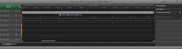
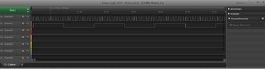
Assuming that channel 1 is the output, it appears to be something like 900kHz.
What happens if you keep the original code I.E.
Code:
'18F4431 32MHz XTL REMOTE_SLAVE 164 389 030223 1200
Define CONFIG1L = 0x00
Define CONFIG1H = 0x06  '8mHz XTL x4 =32mHz
Define CONFIG2L = 0x0c
Define CONFIG2H = 0x20
Define CONFIG3L = 0x04
Define CONFIG3H = 0x80
Define CONFIG4L = 0x80  'Set for HVP
Define CONFIG4H = 0x00
Define CONFIG5L = 0x0f
Define CONFIG5H = 0xc0
Define CONFIG6L = 0x0f
Define CONFIG6H = 0xe0
Define CONFIG7L = 0x0f
Define CONFIG7H = 0x40

Define CLOCK_FREQUENCY = 32

'Define SIMULATION_WAITMS_VALUE = 1  'Comment in for SIM out for PIC

Dim wordTemp As Word

OSCCON = %01110000  '& h70
TRISA = %11000000   '7=OSC, 6=OSC,
TRISC = %11111010   '6=1-slave4431_cs, 2=74HC164 CLK, 0=74HC164 DATA
wordTemp = 0
CCPR1H=wordTemp.HB
CCPR1L=wordTemp.LB
CCP1CON=0b1000
T1CON = 1           'timer 1 started
While 1             'loop forever
  If PIR1.CCP1IF Then
    Toggle CCP1CON.0
    wordTemp=wordTemp+4000
    CCPR1H=wordTemp.HB
    CCPR1L=wordTemp.LB
    PIR1.CCP1IF=0
  Endif
Wend
End
The above is different to #444 as I edited that but didn't think it mattered as it (the BBS) said you'd not visited since the previous day. I added T1CON=1 which your code doesn't have so I guess you visited but weren't logged in.
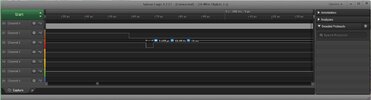
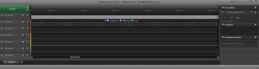
Does the above make a 1kHz output on RC2? Note, the order of instructions is important. In this case it's important that CCPR1H is written before CCPR1L.
Generating a frame time will not work as it can be as long as 12mS (20-8*1mS) or 96,000 clock cycles and the maximum time that can be added in one go is 65,535 cycles. It could be done by dividing by two and adding it twice but the timer 2 interrupt shouldn't cause any problems.
Mike.
Edit, I've corrected the typos. I.E. wordTemp.
")